Analysis of the Causes of Cracks in the Welded Joints of Tees in a Power Plant (Part One)
Posted: 10/16/2021 10:24:51 Hits: 44
The main steam pipe is an important part of the boiler steam and water system, and its stress is complicated at the tee and its connecting part, which is the weak part of the main steam pipe. A certain power plant has been operating for 8×10⁴ hours. Cracks were found at the tee of the steam turbine platform of the main steam pipeline during the overhaul. The power plant verified that there were multiple cracks at the welding seam of the tee, and repair welding was performed in the power plant. The main steam tee is an equal tee. The end size is ϕ377 × 50 mm. The design temperature is 565°C, and the design pressure is 13.7MPa. The main steam pipe is made from 15Cr1Mo1V steel. The chromium element is added to the steel to improve the oxidation resistance of the steel, and the molybdenum and vanadium elements are added to improve the thermal strength of the steel. This material is mainly used for the main steam pipe and header with a wall temperature less than and equal to 580℃ for a long time. The welding material is R317 heat-resistant steel electrode. The welding joint of the tee with cracks was inspected and analyzed to find out the cause of the cracks and avoid similar failures from happening again.
Physical and chemical tests
Physical and chemical tests
1. Non-destructive testing
The non-destructive test was performed for the welding seam of the main steam tee. The results are shown in Figure 1. It can be seen that a full circle of cracks appeared at the welding seam, and the cracks expanded along the fusion line at the welding toe of the welding seam.
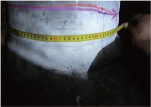
Figure 1 The macro morphology of the crack of the tee
2. The hardness test
The on-site Brinell hardness test was performed on the base material, welding seam and heat-affected zone near the tee. The test location is shown in Figure 2, and the test results are shown in Table 1.
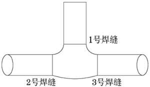
Figure 2 The schematic diagram of locations of tees subjected to hardness tests
Table 1 Hardness test results of tees

Figure 1 The macro morphology of the crack of the tee
2. The hardness test
The on-site Brinell hardness test was performed on the base material, welding seam and heat-affected zone near the tee. The test location is shown in Figure 2, and the test results are shown in Table 1.

Figure 2 The schematic diagram of locations of tees subjected to hardness tests
Table 1 Hardness test results of tees
| Items | Testing locations | Hardness/HB |
| No. 1 welding seams |
Upper base materials | 140 |
| Upper heat affected zones | 182 | |
| No. 1 welding seams | 187 | |
| Lower heat affected zones | 182 | |
| Lower base materials | 144 | |
| No. 2 welding seams | Left base materials | 148 |
| Left heat affected zones | 182 | |
| No. 2 welding seams | 192 | |
| Right heat affected zones | 181 | |
| Right base materials | 146 | |
| No. 3 welding seams | Right base materials | 148 |
| Right heat affected zones | 172 | |
| No. 3 welding seams | 193 | |
| Right heat affected zones | 179 | |
| Right base materials | 150 | |
| Standard values | 145 to 200 |
It can be seen from Table 1 that the hardness of the base material of the 15Cr1Mo1V steel main steam pipeline part is close to or lower than the lower limit of the technical requirements for 15Cr1Mo1V steel in the electric power industry standard DL/T438-2016 Metal Technical Supervision Regulations for Thermal Power Plants.
3. Metallographic inspection
The metallographic inspection was performed on samples near the cracks. The results of the inspection are shown in Figure 3. It can be seen that the microstructures near the cracks were all bainite. Carbides precipitated and aggregated at the grain boundary and in grain. No creep holes were found, and different degrees of aging appear in the microstructure. The aging grade is grade 4.
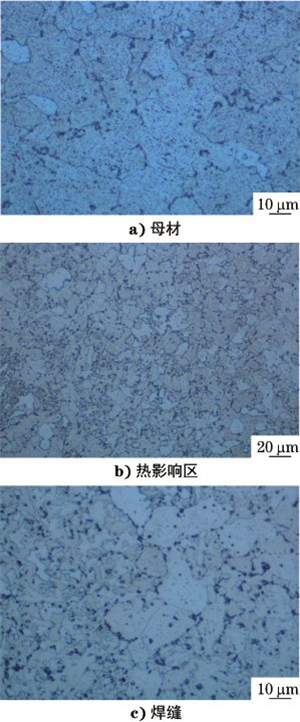
Figure 3 The microstructure morphology of welded joints
4. Stress calculation and analysis of main steam piping systems
Stress calculation and analysis of piping systems
The on-site inspection found that the NO. 150 sliding support under the tee 12 meters away from the steam engine room of the main steam pipeline was hindered in a thermal operation, and the displacement of the pipeline in a thermal state was insufficient. The limit position appeared for nearby pipeline supports and hangers, as shown in Figure 4.
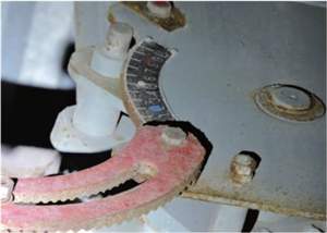
Figure 4 The spring pointer being at the limit position
The rationality of operation of the support and hanger will directly affect the stress distribution of the piping system and thrust of the equipment's endpoint. Given this, according to design parameters of pipelines, structural forms and distribution of supports and hangers, the stress calculation of the pipeline was carried out on the pipe system where the tee was located, and the stress distribution of the pipe system and the thrust and moment of the pipe system to the piping system near the tee were obtained as the boundary conditions of structural analysis of tees, compared with the stress calculation results under normal sliding conditions. The stress model of the main steam pipeline was established as shown in Figure 5.
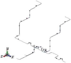
Figure 5 The calculating model of the main steam pipeline
It can be seen from the calculation of the pipe stress that the position of the broken tee was the position where the bending stress and torsion stress of the pipe system were the maxima. The comparison of the calculation results of the pipe system's stress is shown in Table 2. It can be seen from Table 2 that when the No. 105 sliding support under the tee was hindered, the maximum primary stress and secondary stress of the piping system increase. Among them, the bending stress and torsion stress near the welding seam of the tee increase the most, with a maximum increase of 32 %.
Table 2 Calculating results of the piping stress
The on-site inspection found that the NO. 150 sliding support under the tee 12 meters away from the steam engine room of the main steam pipeline was hindered in a thermal operation, and the displacement of the pipeline in a thermal state was insufficient. The limit position appeared for nearby pipeline supports and hangers, as shown in Figure 4.

Figure 4 The spring pointer being at the limit position
The rationality of operation of the support and hanger will directly affect the stress distribution of the piping system and thrust of the equipment's endpoint. Given this, according to design parameters of pipelines, structural forms and distribution of supports and hangers, the stress calculation of the pipeline was carried out on the pipe system where the tee was located, and the stress distribution of the pipe system and the thrust and moment of the pipe system to the piping system near the tee were obtained as the boundary conditions of structural analysis of tees, compared with the stress calculation results under normal sliding conditions. The stress model of the main steam pipeline was established as shown in Figure 5.

Figure 5 The calculating model of the main steam pipeline
It can be seen from the calculation of the pipe stress that the position of the broken tee was the position where the bending stress and torsion stress of the pipe system were the maxima. The comparison of the calculation results of the pipe system's stress is shown in Table 2. It can be seen from Table 2 that when the No. 105 sliding support under the tee was hindered, the maximum primary stress and secondary stress of the piping system increase. Among them, the bending stress and torsion stress near the welding seam of the tee increase the most, with a maximum increase of 32 %.
Table 2 Calculating results of the piping stress
| Locations | Stress | The calculation result of the stress/MPa | The increase of the stress/% | |
| Design states | Displacement being hindered | |||
| Piping systems | Maximum primary stress | 41.3 | 48.0 | 16 |
| Piping systems | Maximum secondary stress | 122.0 |
145.4 |
19 |
| Bending stress (The cold state) | 32.0 |
41.9 |
30 |
|
| Tees | Bending stress (The hot state) | 43.0 |
52.0 |
21 |
| Welding seam parts | Torsional stress (The cold state) | 10.1 |
13.3 |
31 |
| Torsional stress (The hot state) | 14.6. |
19.3 |
32 | |
Post URL: https://www.landeepipefitting.com/analysis-of-the-causes-of-cracks-in-the-welded-joints-of-tees-in-a-power-plant-part-one.html
Landee is a professional industrial pipe fitting manufacturer and be well accepted by customers all over the world, we has been producing Pipe Fitting for a variety of applications since 1985. welcome to access our website: https://www.landeepipefitting.com.
Previous: The Cause of the Leakage of the Tee and Its Solution
Next: Analysis of the Causes of Cracks in the Welded Joints of Tees in a Power Plant (Part Two)
Next: Analysis of the Causes of Cracks in the Welded Joints of Tees in a Power Plant (Part Two)
