Analysis of the Causes of Cracks in the Welded Joints of Tees in a Power Plant (Part Two)
Posted: 10/22/2021 11:04:58 Hits: 156
Calculation and analysis of thrust force of pipe systems to pipe ends connected to tees
When the sliding bracket is hindered or can be operated, the comparison results of the thrust and torque of the pipe system to the pipe end connected to the tee are shown in Table 3. In the table, Fx, Fy, Fz represent the thrust of the pipe system to the pipe end connected to the tee in the x-axis, y-axis, z-axis. The X-direction is along the pipeline axis. Y-direction is vertical, and z-direction is horizontal and vertical to the pipeline axis.
Table 3 Calculation results of the thrust of the pipe system to the pipe end connected to the tee
| Working conditions | Locations | Items | Displacement in a hindered state/N | Design states/N | Increase/% |
| In a cold state | The upper side connecting pipe end of the tee | Fx | 8 556.92 | 6532 | 31.00 |
| Fy | 34 303.68 | 33 164 | 3.44 | ||
| Fz | 4093.56 | 2988 | 37.00 | ||
| The left side connecting pipe end of the tee | Fx | 8823.20 | 6629 | 33.10 | |
| Fy | 9744.14 | 9 715 | 0.30 | ||
| Fz | 21469.32 | 15 998 | 34.20 | ||
| The right side connecting pipe end of the tee | Fx | 198.00 | 197 | 0.50 | |
| Fy | 35359.76 | 35 254 | 0.30 | ||
| Fz | 25 667.43 | 18 887 | 35.90 | ||
| In a hot state | The upper side connecting pipe end of the tee | Fx | 14 498.39 | 10132 | 43.10 |
| Fy | 35 725.73 | 35 229 | 1.41 | ||
| Fz | 6314.42 | 4240 | 48.93 | ||
| The left side connecting pipe end of the tee | Fx | 14 351.00 | 1 0029 | 43.10 | |
| Fy | 9849.98 | 9800 | 0.51 | ||
| Fz | 40931.72 | 27788 | 47.30 | ||
| The right side connecting pipe end of the tee | Fx | 200.50 | 1.27 | 198 | |
| Fy | 96 155.60 | 95 868 | 0.30 | ||
| Fz | 34 617.91 | 23548 | 47.01 |
Through the calculation and comparison of the piping stress, it can be seen that the bending stress of the piping system at the tee is the greatest. When the sliding support is hindered, the thermal displacement of the piping is hindered, which affects the stress state of the piping system. Both the primary stress and secondary stress increase. The bending stress and torsion stress near the tee increase greatly. This also affects the changes of thrust and moment of force of the pipeline system on the upper, left, and right connecting ends of the tee, especially the axial direction of the pipeline in a hot state. The stress for x-direction and z-direction horizontally perpendicular to the pipe increases significantly, and the maximum increase is 48.93%.
5. Finite element analysis under internal pressure and structural stress
Geometric models
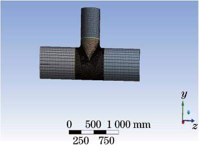
Finite element analysis uses mathematical approximation methods to simulate real physical systems. It has become an effective way to solve problems of complex engineering analysis and calculation. Finite element analysis methods are used to simulate the tee. The main pipe of the tee and branch pipe axis is on a common plane, which is the geometric plane of symmetry. Using geometric symmetry, the finite element model is divided into half of the tees. The model is divided into 7 parts, namely the tee, the three sides connecting to welding seams, and the base metals on the three sides. The finite element model uses hexahedral elements to finely divide the tee and connecting parts of welding seams. The total number of elements is 61193 and the total number of nodes is 21946. The finite element model and the mesh division of the elements of the tee are shown in Figure 6.

Figure 6 The schematic diagram of grid division of the tee
Constraints and loading
In Figure 6, the limit displacement constraint is applied in the y-direction (y=0), and the structural stress generated by the system is input on the end face of the model (see Table 3). The internal pressure of 13.7MPa is uniformly applied on the inner surface of the model, and the equivalent stress is input on the end face of the model; the formula is as follows:
F=πR2p(1)
In the formula, F is the equivalent stress on the end face of the model; p is the internal pressure; R is the radius of the tee.
Solution results and distribution laws
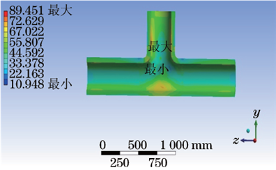
The finite element simulation calculation results of the tee are shown in Figure 7. It can be seen from Figure 7 that under the comprehensive conditions of the model, the maximum stress area is located at the area where the tee and the upper weld are connected; the maximum stress value is 89.4MPa, and the maximum stress area is consistent with the crack position.

Figure 7 Stress distribution diagrams of finite element simulation of tees
Analysis and discussion
From the point of view of the crack's location, the crack is located at the welding part of the tee of the main steam tee, and the crack expands along the fusion line at the welding toe, forming almost a full circle of cracks. From the hardness test and microscopic analysis, the hardness of the tee is low, lower than or close to the lower limit of the standard requirement, and the microstructure is bainite. However, the microstructure shows different degrees of aging, and the aging rating is grade 4. It is speculated that the mechanical properties of the material are degraded due to long-term operation.
The stress analysis of the piping system shows that the bending stress and torsion stress of the piping system are the greatest at the welding part of the tee. When the sliding support under the tee is hindered, the stress at the welding part of the tee increases significantly, with a maximum increase of 32%. Therefore, cracks often happen at the welding part of the tee for the piping system.
The finite element analysis of the tee and the connecting pipe shows that the maximum stress point is at connecting part of the tee and the upper welding seam, and the maximum stress is 89.45MPa; no cracks appear near the tee. Samples were taken at the welding part of the tee, and the isothermal extrapolation was used to calculate the high-temperature endurance strength of the welded joint after operating for 8×10⁴ hours, which was 86MPa. It can be seen that the maximum stress at the welding seam exceeds the high-temperature endurance strength of the material, so creep cracking occurs.
Conclusions and recommendations
The piping arrangement near the tee is unreasonable; the bending stress at the welded joint is great and there is stress concentration. The maximum stress exceeds the high-temperature endurance strength of the welded joint, and the microstructure at the crack is aging; the mechanical properties of the welded joint are reduced, resulting in creep cracking. It is recommended that the cracked tee should be replaced in time, and strengthen the metallographic inspection of the tee and welded joints in the daily inspection.
Post URL: https://www.landeepipefitting.com/analysis-of-the-causes-of-cracks-in-the-welded-joints-of-tees-in-a-power-plant-part-two.html
Landee is a professional industrial pipe fitting manufacturer and be well accepted by customers all over the world, we has been producing Pipe Fitting for a variety of applications since 1985. welcome to access our website: https://www.landeepipefitting.com.
Previous: Analysis of the Causes of Cracks in the Welded Joints of Tees in a Power Plant (Part One)
Next: Classifications and Characteristics of Reducers
Next: Classifications and Characteristics of Reducers
