Application & Failure of Expansion Joints in High-Temperature Flue Gas Pipes
Posted: 09/17/2024 12:36:06 Hits: 28
On this page
Introduction
During the operation of petrochemical pipelines, the combined influence of ambient temperature, fluid temperature, and pressure changes often causes vibrations and displacements, adversely affecting the safe operation of connected equipment and the sealing performance of the pipeline. Therefore, flexible compensation is typically adopted in pipeline design to absorb or transfer displacement caused by pipeline vibration, thermal expansion, and contraction. Common flexible compensation methods include natural compensation and compensator compensation. Natural compensation mainly utilizes the flexible layout of the pipeline, with common layouts including Z-type, L-type, and π-type. Compensator compensation, including the expansion joints discussed in this article, absorbs pipeline vibration and displacement by adding elastic elements to the pipeline.
Metal bellows expansion joints offer advantages such as large compensation capacity, small space requirements, and easy maintenance. They are widely used in high-temperature, long-distance, thermal, and large-diameter pipelines in coal-to-gas, coal-to-olefins, catalytic cracking, and other processes. Based on whether the expansion joint can withstand the internal pressure blind plate force, bellows expansion joints are classified as constrained or unconstrained. Constrained expansion joints can withstand the internal pressure blind plate force and primarily include single hinge type, single universal hinge type, compound hinge type, compound universal hinge type, compound tie rod type, and pressure balance type. Unconstrained expansion joints cannot withstand the blind plate force and primarily include external pressure axial type, single axial type, and proportional connecting rod compound free type.
Metal bellows expansion joints offer advantages such as large compensation capacity, small space requirements, and easy maintenance. They are widely used in high-temperature, long-distance, thermal, and large-diameter pipelines in coal-to-gas, coal-to-olefins, catalytic cracking, and other processes. Based on whether the expansion joint can withstand the internal pressure blind plate force, bellows expansion joints are classified as constrained or unconstrained. Constrained expansion joints can withstand the internal pressure blind plate force and primarily include single hinge type, single universal hinge type, compound hinge type, compound universal hinge type, compound tie rod type, and pressure balance type. Unconstrained expansion joints cannot withstand the blind plate force and primarily include external pressure axial type, single axial type, and proportional connecting rod compound free type.
1. High-Temperature Flue Gas Pipeline and Expansion Joint
1.1 Pipeline Process Description
The methanol-to-olefins (MTO) unit is one of the core devices in coal-to-olefin technology and is usually composed of a reaction-regeneration system, quenching water washing system, sewage stripping system, public utilities, and thermal system. The regeneration system is the core component of the device. In the reactor, gas-phase methanol reacts in the presence of a catalyst to produce low-carbon olefin molecules and by-products primarily composed of ethylene and propylene. At the same time, a small amount of coke is produced, which adheres to the catalyst surface and causes deactivation. The deactivated catalyst is transported to the regenerator, where it is burned to restore its activity. The regenerator burns coke to produce approximately 43,000 Nm³ of regenerated flue gas, with an operating temperature of 670°C and an operating pressure of around 0.07MPa. The gas contains CO and CO₂, which are transported to the thermal system through the flue gas pipeline to fully burn CO, recover heat, and finally discharge it into the atmosphere. The flue gas pipeline is approximately 200 meters long and uses a cold-wall design. The pipeline is equipped with a heat-insulating, wear-resistant double-layer lining, which reduces the outer wall temperature to below 200°C, thereby improving the pipeline's safety. The pipeline is made from SA672-C70 welded carbon steel, significantly reducing material costs.
1.2 Forms and Layout of Flue Gas Expansion Joints
The flue gas pipeline of the MTO device covers a long distance, with a large pipeline diameter, a significant temperature difference between hot and cold states, and a substantial amount of flue gas transported. The pipeline experiences significant thermal expansion displacement during operation. Therefore, multiple metal bellows expansion joints are installed in the flue gas pipeline to absorb displacement and vibration. The primary types of expansion joints used are the single axial type and the proportional connecting rod compound free type. Both are classified as free-type expansion joints. The bellows are made from Incoloy 800, a high-temperature, corrosion-resistant alloy with excellent corrosion resistance, strength, and processing performance.
Based on force characteristics, the single axial expansion joint consists of a section of bellows and structural components and is mainly used to absorb axial displacement, though it cannot withstand internal pressure from the blind plate force. The proportional connecting rod compound free expansion joint consists of an intermediate pipe that connects two sections of bellows, proportional connecting rods, and other structural components. It is primarily used to absorb both axial and lateral combined displacements. According to GB/T 12777-2019 "General Technical Conditions for Metal Bellows Expansion Joints," it cannot withstand the internal pressure caused by the blind plate force on the bellows. Therefore, when the expansion joint is installed in the flue gas pipeline, a fixed support and a guide support are provided to ensure its effective use.

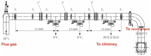
Figure 1 Layout of Flue Gas Pipelines
Figure 1 illustrates the layout of the flue gas pipeline, extending from the double-acting slide valve to the thermal system. The pipeline is approximately 60 meters in length, with the operating pressure reduced to around 0.007 MPa. Expansion joints 1#, 2#, and 3# are installed, all of which are single axial expansion joints primarily used to absorb axial displacement. S1, S5, and S7 are fixed supports, primarily bearing the blind plate force of the bellows, displacement elastic force, medium flow, and other forces resulting from pipeline loads. S2, S3, S4, and S6 are guide supports. According to GB/T 35979-2018, "Technical Specifications for Selection, Installation, Use and Maintenance of Metal Bellows Expansion Joints," the pipeline is only permitted to move freely in the axial direction. The flue gas pipeline leads to the incinerator or chimney through a tee and an elbow. Fixed supports are installed after the tee and the elbow to bear part of the pipeline’s axial force and ensure the overall stability of the flue gas pipeline.
The internal pressure blind plate force of the flue expansion joint can be calculated using the following formula:

Where p is the pipeline medium pressure in Newtons (N), and A is the effective cross-sectional area of the bellows in square millimeters (mm²), calculated as A = πdm²/4 (where dm is the average diameter of the bellows in millimeters). The average diameter of the bellows, dm, is 1690 mm, and the flue gas pipeline pressure, p, is approximately 0.007MPa. Under normal working conditions, the internal pressure blind plate force of the expansion joint is calculated to be 15,694.3 N, approximately 1,570 kg of thrust. The blind plate force is proportional to the internal pressure. The designed thrust load for the fixed support S1 is 5,500 kg, which fully meets the requirements for the safe operation of the pipeline and bellows expansion joints.
Based on force characteristics, the single axial expansion joint consists of a section of bellows and structural components and is mainly used to absorb axial displacement, though it cannot withstand internal pressure from the blind plate force. The proportional connecting rod compound free expansion joint consists of an intermediate pipe that connects two sections of bellows, proportional connecting rods, and other structural components. It is primarily used to absorb both axial and lateral combined displacements. According to GB/T 12777-2019 "General Technical Conditions for Metal Bellows Expansion Joints," it cannot withstand the internal pressure caused by the blind plate force on the bellows. Therefore, when the expansion joint is installed in the flue gas pipeline, a fixed support and a guide support are provided to ensure its effective use.

Figure 1 Layout of Flue Gas Pipelines
Figure 1 illustrates the layout of the flue gas pipeline, extending from the double-acting slide valve to the thermal system. The pipeline is approximately 60 meters in length, with the operating pressure reduced to around 0.007 MPa. Expansion joints 1#, 2#, and 3# are installed, all of which are single axial expansion joints primarily used to absorb axial displacement. S1, S5, and S7 are fixed supports, primarily bearing the blind plate force of the bellows, displacement elastic force, medium flow, and other forces resulting from pipeline loads. S2, S3, S4, and S6 are guide supports. According to GB/T 35979-2018, "Technical Specifications for Selection, Installation, Use and Maintenance of Metal Bellows Expansion Joints," the pipeline is only permitted to move freely in the axial direction. The flue gas pipeline leads to the incinerator or chimney through a tee and an elbow. Fixed supports are installed after the tee and the elbow to bear part of the pipeline’s axial force and ensure the overall stability of the flue gas pipeline.
The internal pressure blind plate force of the flue expansion joint can be calculated using the following formula:

Where p is the pipeline medium pressure in Newtons (N), and A is the effective cross-sectional area of the bellows in square millimeters (mm²), calculated as A = πdm²/4 (where dm is the average diameter of the bellows in millimeters). The average diameter of the bellows, dm, is 1690 mm, and the flue gas pipeline pressure, p, is approximately 0.007MPa. Under normal working conditions, the internal pressure blind plate force of the expansion joint is calculated to be 15,694.3 N, approximately 1,570 kg of thrust. The blind plate force is proportional to the internal pressure. The designed thrust load for the fixed support S1 is 5,500 kg, which fully meets the requirements for the safe operation of the pipeline and bellows expansion joints.
2. Stable Failure of Expansion Joint and Its Impact
2.1 Stable Failure
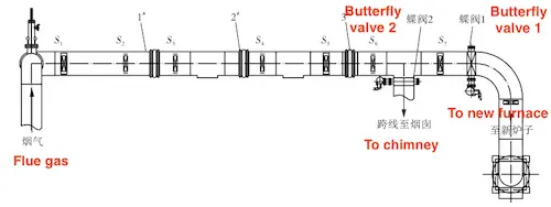
With the increasing environmental protection requirements, the flue gas incineration and waste heat recovery process of the MTO unit has been upgraded for energy conservation and environmental compliance. A full-load CO incinerator was added downstream of the flue gas pipeline to recover waste heat and chemical energy from CO combustion, which is then used to superheat saturated medium-pressure steam and heat medium-pressure boiler feed water. To prepare for the elimination and dismantling of outdated and inefficient equipment, the old waste boiler was disconnected from the three-way branch of the flue gas pipeline during a shutdown inspection. The pipeline structure following the transformation is shown in Figure 2.

Figure 2
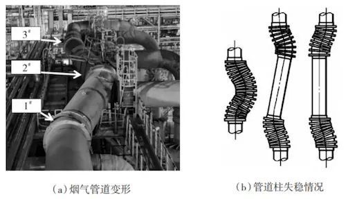
During the start-up process, the flue gas pipeline became severely misaligned, with the pipeline support displaced and suspended, resulting in the loss of support and thrust. The bellows expansion joint was severely elongated and deformed, with local elongation reaching one-third of the expansion joint's length, exceeding 20% of the wave distance (see Figure 3 (a)). According to the failure classification of bellows expansion joints in GB/T 35979-2018, this is a typical case of stable failure (see Figure 3 (b)).

(a) Deformation of the flue gas pipeline (b) Instability of the pipeline column
Figure 3

Figure 2
During the start-up process, the flue gas pipeline became severely misaligned, with the pipeline support displaced and suspended, resulting in the loss of support and thrust. The bellows expansion joint was severely elongated and deformed, with local elongation reaching one-third of the expansion joint's length, exceeding 20% of the wave distance (see Figure 3 (a)). According to the failure classification of bellows expansion joints in GB/T 35979-2018, this is a typical case of stable failure (see Figure 3 (b)).

(a) Deformation of the flue gas pipeline (b) Instability of the pipeline column
Figure 3
2.2 Impact of Stable Failure
The deformation of the expansion joint generates severe tensile and compressive stresses, effectively causing it to lose its ability to absorb pipeline displacement and vibration. When the expansion joint is used again, it may cause stress cracking of the bellows. Additionally, after the expansion joint is stretched or compressed, the position of the internal guide tube changes. The guide tube functions as an internal protective element. In principle, it should be designed as short as possible to avoid vibration of the cantilever structure caused by fluid flow. However, when the expansion joint reaches maximum displacement, the guide tube must completely cover the bellows to effectively divert fluid and protect the bellows from scouring. Because there is an almost closed cavity between the guide tube and the bellows, the gas medium remains static, resulting in minimal convective heat transfer. The gas has low thermal conductivity, which further limits heat transfer. Therefore, the guide tube provides a cooling effect, which is crucial for preventing fatigue failure, high-temperature corrosion, and extending the service life of the bellows. As the distance between the tail of the guide tube and the baffle ring increases, the bellows become directly exposed to high-temperature flue gas containing solid particles (catalyst powder). Chemical components in the flue gas, such as O, S, Cl⁻, and NOx, cause damage or corrosion to the surface of the bellows, exacerbating stress corrosion failure of the bellows material.
Research indicates that when Incoloy 800 alloy is used for an extended period in the temperature range of approximately 500–650°C, Cr-rich carbides precipitate at the grain boundaries, increasing the alloy's brittleness. Simultaneously, Cr-poor regions form in the matrix on both sides of the grain boundaries, creating conditions for selective subcutaneous oxidation and sulfur absorption corrosion. Oxidative corrosion weakens the strength of grain boundaries. Under stress, microcracks form at the grain boundaries, which further promote corrosion. As pipeline stress increases, the bellows may quickly fail due to brittle fracture. Therefore, the instability and deformation of the expansion joint significantly reduce its service life and ability to absorb axial displacement, while increasing the risk of corrosion cracking and leakage, posing a serious threat to the safe operation of the pipeline.
Research indicates that when Incoloy 800 alloy is used for an extended period in the temperature range of approximately 500–650°C, Cr-rich carbides precipitate at the grain boundaries, increasing the alloy's brittleness. Simultaneously, Cr-poor regions form in the matrix on both sides of the grain boundaries, creating conditions for selective subcutaneous oxidation and sulfur absorption corrosion. Oxidative corrosion weakens the strength of grain boundaries. Under stress, microcracks form at the grain boundaries, which further promote corrosion. As pipeline stress increases, the bellows may quickly fail due to brittle fracture. Therefore, the instability and deformation of the expansion joint significantly reduce its service life and ability to absorb axial displacement, while increasing the risk of corrosion cracking and leakage, posing a serious threat to the safe operation of the pipeline.
Post URL: https://www.landeepipefitting.com/application-failure-of-expansion-joints-in-high-temperature-flue-gas-pipes.html
Landee is a professional industrial pipe fitting manufacturer and be well accepted by customers all over the world, we has been producing Pipe Fitting for a variety of applications since 1985. welcome to access our website: https://www.landeepipefitting.com.
Previous: Effect of Flow Rates on Erosion of Inner Walls of Bends
Next: Optimal Design of Expansion Joints in High-Temperature Flue Gas Pipes
Next: Optimal Design of Expansion Joints in High-Temperature Flue Gas Pipes
