Abstract
A leak was detected in the reducers of the high-pressure heater located in the conventional island of a nuclear power plant. The chemical composition, microstructure, hardness, fracture morphology, and elemental distribution of the reducers in the liquid level switch were analyzed through macroscopic and microscopic examination. Results indicate that the carbon content in the base material of the reducers in the liquid level switch significantly exceeds the standard, whereas the nickel and molybdenum levels are below the required specifications, resulting in intergranular stress corrosion cracking.
Introduction
Nuclear energy is a reliable, clean, and highly efficient power source. As a key component of the global energy mix, it plays a vital role in the world's energy infrastructure. Operational data from pipelines in light water reactor nuclear power plants worldwide, totaling over 12,000 reactor-years of operation, indicate that the primary failure mechanisms are flow-accelerated corrosion (FAC) and stress corrosion cracking (SCC), which account for over 50% of pipeline failures in nuclear power plants. Vibration fatigue accounts for 18.7%, while crevice corrosion, pitting corrosion, and microbial corrosion collectively make up 14.8%.
China's nuclear power industry has been in commercial operation for over 20 years. With the advancement of domestic nuclear power, significant progress has been made in the design, construction, equipment manufacturing, and operational experience of nuclear power plants, leading to technological maturation. However, failures in nuclear power plant equipment and materials have become more frequent, making issues with plant components increasingly evident.
The Daya Bay Nuclear Power Plant previously experienced a weld fracture between the safety valve, the electric head sleeve, and the two pivots, resulting in the pivots detaching from the sleeve. Analysis indicates that the actuator failure was caused by fatigue fracture, primarily due to the inappropriate use of Stellite alloy as a welding filler material for carbon steel components. At Fuqing Nuclear Power Plant, the instrument casing failed due to fatigue fracture, which was triggered by residual welding stress and exacerbated by fluid-induced vibration fatigue. Similarly, the bursting disc of the low-pressure cylinder at Qinshan Nuclear Power Plant experienced fatigue fracture, originating from the creep susceptibility of pure lead.
During the operation of Unit 1 in the conventional island of a nuclear power plant, a leak was detected at the float level switch of the No. 6 high-pressure heater. The leak originated at the reducer of the level switch, with water droplets seeping from the crack, as shown in Figure 1.
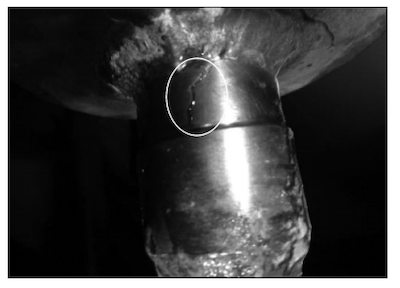
Figure 1 The failed reducer
This study investigates the cause of the reducer failure in the level switch through macroscopic and microscopic analysis.
1. Structure and Working Conditions of Reducers
After exiting the turbine, the steam condenses into water in the condenser. Due to its low temperature, the condensate must be reheated by multiple heaters before returning to the steam generator for steam production. The tube side of the heat exchanger contains condensate, while the shell side holds hot steam. As the steam transfers heat to the condensate, it condenses into drain fluid. To maintain an optimal drain level and ensure stable heater operation, a level switch continuously monitors the drain fluid level. The failed high-pressure heater shell-side drain level switch is equipped with a reducer, as shown in Figure 2.
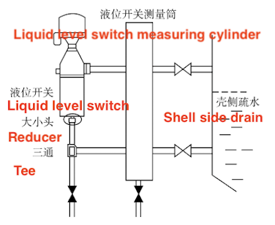
Figure 2 The position of the reducer
The reducer is connected to the level switch measuring cylinder via a branch pipe and a tee. It is made of SS316L stainless steel, with specifications of Φ36 mm × 1/4″, as shown in Table 1. The level switch cylinder has a nominal diameter of DN100 and features a Φ28 mm opening at the bottom. The small end of the reducer is inserted into the opening, while the large end is welded to the tee through a 1″ conduit. Both ends of the reducer are socket welded.
Gas tungsten arc welding (GTAW) is performed using ER316L welding wire (Φ2.0 mm) , with a voltage range of 8–18 V, a current of 80–120 A, a welding speed of 6–15 cm/min, and an argon gas flow rate of 5–25 L/min. The high-pressure heater level switch operates at a maximum temperature of 211°C and a maximum pressure of 1.847 MPa, with condensate serving as the process medium on the shell side.
Table 1 Material and operating conditions of reducers
|
Workpiece |
Specification |
Material |
Maximum Operating Temperature (°C) |
Maximum Operating Pressure (MPa) |
Process Medium |
|
High-pressure heater level switch reducer |
Φ36 mm×4/1″ |
SS316L |
211 |
1.847 |
Water/steam |
The system uses demineralized water, with pH adjusted by adding ammonia and oxygen content controlled by adding hydrazine. During normal operation, the pH is maintained between 8.0 and 11.0, and dissolved oxygen remains below 10 μg/L. Table 2 presents the results of the chemical composition analysis of the water. The chemical parameters of the demineralized water are within operational limits, with corrosion-related cations (such as iron and sodium) and anions (such as chloride and sulfate) well below the threshold values, indicating no signs of abnormal corrosion in the system. Key indicators of a corrosive environment, such as dissolved oxygen (DO) and pH, remain within acceptable limits, eliminating the possibility of rupture due to unfavorable chemical conditions.
Table 2 Chemical limits of operating water of reducers
|
Parameters |
Measurement Value |
Operation Limit |
Index Description |
|
Cl⁻ |
0.100 μg/L |
≤10 μg/L |
Corrosion-related anion monitoring index |
|
DO |
0.5 μg/L |
<10 μg/L |
Dissolved oxygen levels and factors influencing corrosion |
|
Fe³⁺ |
0.7 μg/L |
≤50 μg/L |
Corrosion cation index |
|
Na⁺ |
2.582 μg/L |
<5 μg/L |
Corrosion cation index |
|
pH value |
9.18 |
8-11 |
Factors influencing corrosion |
|
SO₄²⁻ |
0.10 μg/L |
<20 μg/L |
Corrosion anion index |
2. Failure Analysis
Three failed reducer were analyzed:
- Sample No. 1: Bottom reducer of the 6B high-pressure LS1016B heater level switch
- Sample No. 2: Upper reducer of the 6B high-pressure LS1016B heater level switch
- Sample No. 3: Lower reducer of the 6B high-pressure LS1018B heater level switch
Prior to cutting the test samples, a macroscopic inspection of the fracture surface was conducted. Subsequently, chemical composition analysis, metallographic examination, hardness testing, and scanning electron microscopy (SEM) were performed to determine the material failure mechanism.
3. Failure Results and Analysis
3.1 Macro Inspection
Reducers No. 1, No. 2, and No. 3 underwent macro inspection, with the results shown in Figure 3. The overall view of Reducer No. 1 is shown in the upper left of Figure 3a, with both cross-sections being cut surfaces. The top fracture surface covers approximately one-fifth of the circumference, as seen in the upper right of Figure 3a. A section of the catheter remains lodged in the bottom reducer and cannot be removed, as shown in the lower left of Figure 3a. Multiple microcracks were observed in the top and bottom cross sections. Some penetrated the entire wall thickness, while others extended from the inner to the outer wall without full penetration. The cracks on the inner wall are longitudinal, while no visible cracks were detected on the outer wall, as shown in the lower right of Figure 3a.
- The overall image of Reducer No. 2 is shown in the upper left of Figure 3b, with both cross sections being cut surfaces. A microcrack was found on the outer wall, oriented approximately 45° to the axial direction, as shown in the upper right of Figure 3b. Another microcrack was found on the inner wall of the top section, while no cracks were observed in the bottom section, as shown in the lower left and lower right of Figure 3b.
- The overall image of Reducer No. 3 is shown in the upper left of Figure 3c. Both cross sections are cut surfaces, and a non-standard structural modification was introduced when cutting near the top groove. The crack at the top cross section has fully penetrated, and no significant plastic deformation features were observed around the fracture, indicating brittle failure.
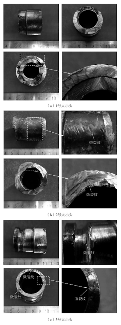
(a) No. 1 reducer (b) No. 2 reducer (c) No. 3 reducer
Figure 3: Macroscopic inspection of the reducers
3.2 Chemical Composition Inspection
The PMI-MASTER Smart spectrometer was used, with a measurement uncertainty of less than 0.002% for C, Cr, and Mo, and less than 0.001% for Si, Mn, V, and Ni. Chemical composition analysis of Reducers No. 1, No. 2, and No. 3 was performed following the GB/T 11170-2008 standard for 'Stainless Steel Spark Source Atomic Emission Spectrometry Analysis.' The test results are shown in Table 3. In reference to ASME SA312, "Standard Specification for Seamless, Welded, and Heavily Cold Worked Austenitic Stainless Steel Pipes," the following are the chemical composition test results of the pipe materials:
- ASME SA312 specifies that the C content in 316L stainless steel must not exceed 0.035%. The C content in Sample No. 1 is 0.230%, while the C content in Samples No. 2 and No. 3 is 0.220%. The C content in all three samples exceeds the acceptable limit.
- ASME SA312 specifies that the Ni content in 316L stainless steel must be between 11.000% and 14.000%. The Ni content in Sample No. 1 is 7.550%, in Sample No. 2 is 7.710%, and in Sample No. 3 is 7.670%. The Ni content in all three samples is below the standard lower limit.
- ASME SA312 specifies that the Mo content in 316L stainless steel must be between 2.000% and 3.000%. The Mo content in Sample No. 1 is 0.100%, in Sample No. 2 is 0.120%, and in Sample No. 3 is 0.120%. The Mo content in all three samples is below the standard lower limit.
- Aside from the excessive C, Ni, and Mo contents discussed above, as well as the slightly elevated Mn content in Sample No. 1, the contents of the other elements in all three samples meet the requirements of ASME SA312.
Table 3 Chemical composition analysis results of reducers
|
Sample |
C (%) |
Si (%) |
Mn (%) |
P (%) |
S (%) |
Cr (%) |
Ni (%) |
Mo (%) |
|
No. 1 |
0.230 |
0.630 |
2.090 |
0.032 |
0.018 |
16.730 |
7.550 |
0.100 |
|
No. 2 |
0.220 |
0.570 |
1.940 |
0.034 |
0.023 |
16.750 |
7.710 |
0.120 |
|
No. 3 |
0.220 |
0.560 |
1.910 |
0.032 |
0.021 |
16.820 |
7.670 |
0.120 |
|
ASME SA312 316L |
≤0.035 |
≤1.000 |
≤2.000 |
≤0.045 |
≤0.030 |
16.000–18.000 |
11.000–14.000 |
2.000–3.000 |
3.3 Metallographic Inspection
Metallographic inspection of the No. 1, No. 2, and No. 3 reducers was conducted using an Axio Observer A3 research-grade inverted microscope. The etching solution used was aqua regia. The inspection was performed in accordance with GB/T 13298-2015, 'Methods for the Inspection of Metal Microstructures.' The metallographic microstructure is shown in Figure 4.
The results of the metallographic inspection are as follows:
- The microstructure of the No. 1 reducer is austenitic, with numerous cracks on the inner wall. These cracks exhibit intergranular cracking and bifurcated morphology, propagating from the inner to the outer wall, as shown in Figure 4a.
- The base metal of the No. 2 reducer is austenitic, while the fillet weld shows a cast austenitic dendritic microstructure. Numerous cracks are present on the inner wall, exhibiting intergranular cracking and bifurcated morphology, propagating from the inner to the outer wall and stopping at the weld seam. No microcracking were observed in the weld seam, as shown in Figure 4b.
- The microstructure of the No. 3 reducer is austenitic. Numerous cracks are present on the inner wall, exhibiting intergranular cracking and bifurcated morphology, propagating from the inner to the outer wall.
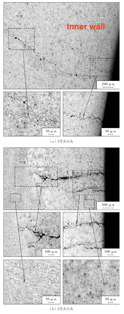
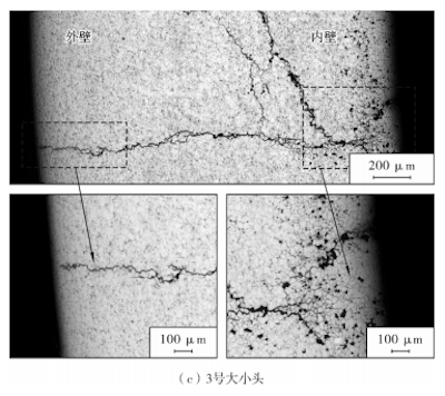
(a) No. 1 reducer (b) No. 2 reducer (c) No. 3 reducer
Figure 4 Metallographic Microstructure of Reducers
3.4 Hardness Test
The Vickers hardness test was performed on the No. 1, No. 2, and No. 3 reducers. The test standard followed was GB/T 4340.1, 'Metallic Materials—Vickers Hardness Test: Part 1—Test Method.' A test force of 100 N was used, with a holding time of 10 seconds. The results are presented in Table 4. The ASME SA312 standard does not specify the hardness values for 316L, but these values are provided in ASME SA213, 'Specification for Seamless Ferritic and Austenitic Alloy-Steel Boiler, Superheater, and Heat-Exchanger Tubes.' The hardness values of the reducers and materials under inspection comply with the ASME SA213 requirements for 316L.
Table 4 Hardness Test Results of the Reducer
|
Sample |
Test Location |
Test Value (HV) |
Average Value (HV) |
|
No. 1 |
Transverse section |
187, 188, 189, and 189 |
188 |
|
No. 2 |
Transverse section |
184, 184, 182, and 184 |
184 |
|
No. 3 |
Transverse section |
187, 202, 198, and 188 |
194 |
|
ASME SA312 316L |
- |
Not specified |
- |
|
ASME SA213 316L |
- |
≤200 HV |
- |
3.5 Microscopic Analysis of Fracture and Microcracks
The fracture and microcrack morphology of the No. 1 reducer were examined using a scanning electron microscope (SEM), and an energy-dispersive spectroscopy (EDS) analysis was performed on the anomalous areas. The SEM images of the fracture surfaces of the No. 1 reducer are shown in Figure 5. The entire fracture surface shows typical intergranular morphology, with numerous secondary cracks visible. The cross-section is covered with corrosion products. Numerous microcracks are present in both the top and bottom sections, all exhibiting intergranular cracking characteristics. The cracks primarily propagate from the inner wall to the outer wall.
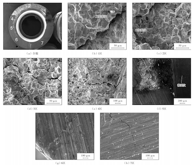
(a) Overall view (b) Zone 1 (c) Zone 2 (d) Zone 3 (e) Zone 4 (f) Zone 5 (g) Zone 6 (h) Zone 7
Figure 5 SEM morphology of the fracture surface of the No. 1 reducer
Additionally, EDS analysis was conducted on crack regions 4 and 5, as shown in Figures 6 and 7. A high concentration of chlorine (Cl) was detected in the corrosion products, suggesting that the material was subjected to a chloride-rich environment.
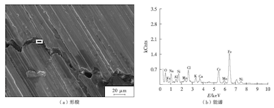
(a) Morphology (b) Energy spectrum
Figure 6 Morphology and energy spectrum of area 4
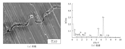
Figure 7 Morphology and energy spectrum of area 5
4. Conclusion
The tests indicate that all cracks in the reducers originate from the base material. Metallographic inspection and scanning electron microscopy (SEM) showed that the cracks exhibited typical intergranular morphology, with several secondary cracks present. The cross-section exhibited corrosion products. Multiple microcracks were observed in the cross-section, all exhibiting intergranular cracking characteristics. The cracks primarily propagate from the inner wall to the outer wall, with significant corrosion products present within the cracks. These findings suggest that the cracking in reducers is intergranular stress corrosion cracking (IGSCC). Chemical composition analysis revealed that the material of reducers did not meet the ASME SA312 standard for 316L, with the carbon (C) content significantly exceeding the specified limit (0.220%–0.230%) by more than five times the upper threshold. Metallographic examination also revealed an increased presence of precipitates at the grain boundaries of the reducers, indicating weak resistance to intergranular corrosion.
Post URL: https://www.landeepipefitting.com/failure-analysis-of-reducers-in-the-high-pressure-heater-of-a-nuclear-power-plant.html
Landee is a professional industrial pipe fitting manufacturer and be well accepted by customers all over the world, we has been producing Pipe Fitting for a variety of applications since 1985. welcome to access our website: https://www.landeepipefitting.com.
