Failure Causes of Tees in Inlet Pipelines of Hydrocracking Pumps(Part One)
Posted: 11/13/2021 08:38:29 Hits: 7
Abstract: Through the macro inspection, chemical analysis, metallographic analysis and scanning electron microscopy analysis of the tee of the stainless steel pipeline at the inlet of the liquefied gas pump of a hydrocracking unit of a certain company. It is believed that the cause of the failure of the tee is the stress corrosion cracking under the combined action of gas ions and hydrogen sulfide in a humid environment. The manufacturing process of the stainless steel tee is not strictly implemented, resulting in the precipitation of σ phase in the metallographic structure, and the solid solution treatment is not performed after manufacturing, making the corrosion resistance of the material worse. Corrosion pits occur in the corrosive medium due to long-term influence of the gas ion and become the source of induced cracks. The mass concentration of the harmful substance hydrogen sulfide has increased from less than 1 g/L in the past to 7 to 10g/L, which has increased sharply, with the mass concentration of chloride ions as high as 124 mg/L. At the same time, the presence of chloride ions in the medium accelerates the stress corrosion rate of hydrogen sulfide, which leads to the failure of the tee.
The pipe tee at the pump inlet of a hydrocracking workshop in a certain company cracked only 2 months after the overhaul. The tee has a size of φ89 mm x 6 mm and is made from 0Cr18Ni9. It is made by integrally compression moulding. The medium in the pipeline is liquefied petroleum gas, and contains hydrogen sulfide, chloride ions and a small amount of water. The pressure is 2.0MPa and the temperature is 30 to 40℃. The hydrogen sulfide content in the medium changes significantly because of the refining of crude oil containing high sulfur. The mass concentration of hydrogen sulfide has increased from less than 1 g/L in the past to 7 to 10 g/L now. The mass concentration of harmful substances hydrogen sulfide has increased sharply, and the mass concentration of chloride ions is as high as 124 mg/L, which is the main cause of corrosion failure.
1. Macro inspection and thickness measurement
1.1 Macro inspection
The surface of the tee was smooth, and cracks appeared symmetrically on both sides of the neck of the tee, which were distributed longitudinally along the neck of the tee. The direction was straight and branching cracks happened. The length of the crack was about 45 mm, and the crack on one side of the cracked tee has been repaired by welding. Cut the tee along the longitudinal direction. The inner surface was inspected macroscopically. The result of the inspection revealed that the inner surface was black, and there were many corrosion pits of different sizes and different depths, as shown in Figure 1. The cracks on the inner wall of the tee were not continuous, but expanded intermittently in steps, as shown in Figure 2. The tee was cut along the crack, and after macroscopic inspection of the fracture, it was found that the crack expanded from the inner wall to the outer wall; the direction was perpendicular to the tee wall. The fracture was flush, and there were steps. The surface of the fracture was corroded and characterized by brittle fracture.
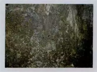
Figure 1 Corrosion pits on the inner wall of the tee
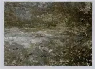
Figure 2 Cracks on the inner wall of the tee
1.2 Thickness measurement
Sixteen points of the inner wall of the tee were selected for macroscopic inspection and the wall thickness test was carried out. The wall thickness of the tee showed no obvious signs of uniform thinning. The thickness measurement results are shown in Table 1.
2. The analysis of the chemical composition
The tee was sampled for chemical composition analysis, and the results were shown in Table 2. The chemical composition of the tee conforms to the chemical composition requirements of 0Cr18Ni9 in the GB1221-92 standard.
Table 1 Thickness values of tees
The pipe tee at the pump inlet of a hydrocracking workshop in a certain company cracked only 2 months after the overhaul. The tee has a size of φ89 mm x 6 mm and is made from 0Cr18Ni9. It is made by integrally compression moulding. The medium in the pipeline is liquefied petroleum gas, and contains hydrogen sulfide, chloride ions and a small amount of water. The pressure is 2.0MPa and the temperature is 30 to 40℃. The hydrogen sulfide content in the medium changes significantly because of the refining of crude oil containing high sulfur. The mass concentration of hydrogen sulfide has increased from less than 1 g/L in the past to 7 to 10 g/L now. The mass concentration of harmful substances hydrogen sulfide has increased sharply, and the mass concentration of chloride ions is as high as 124 mg/L, which is the main cause of corrosion failure.
1. Macro inspection and thickness measurement
1.1 Macro inspection
The surface of the tee was smooth, and cracks appeared symmetrically on both sides of the neck of the tee, which were distributed longitudinally along the neck of the tee. The direction was straight and branching cracks happened. The length of the crack was about 45 mm, and the crack on one side of the cracked tee has been repaired by welding. Cut the tee along the longitudinal direction. The inner surface was inspected macroscopically. The result of the inspection revealed that the inner surface was black, and there were many corrosion pits of different sizes and different depths, as shown in Figure 1. The cracks on the inner wall of the tee were not continuous, but expanded intermittently in steps, as shown in Figure 2. The tee was cut along the crack, and after macroscopic inspection of the fracture, it was found that the crack expanded from the inner wall to the outer wall; the direction was perpendicular to the tee wall. The fracture was flush, and there were steps. The surface of the fracture was corroded and characterized by brittle fracture.

Figure 1 Corrosion pits on the inner wall of the tee

Figure 2 Cracks on the inner wall of the tee
1.2 Thickness measurement
Sixteen points of the inner wall of the tee were selected for macroscopic inspection and the wall thickness test was carried out. The wall thickness of the tee showed no obvious signs of uniform thinning. The thickness measurement results are shown in Table 1.
2. The analysis of the chemical composition
The tee was sampled for chemical composition analysis, and the results were shown in Table 2. The chemical composition of the tee conforms to the chemical composition requirements of 0Cr18Ni9 in the GB1221-92 standard.
Table 1 Thickness values of tees
| Positions | Values | Positions | Values | Positions | Values | Positions | Values |
| 1 | 8.3 | 5 | 8.5 | 9 | 9.0 | 13 | 6.2 |
| 2 | 8.3 | 6 | 8.3 | 10 | 8.9 | 14 | 6.3 |
| 3 | 8.4 | 7 | 8.9 | 11 | 6.4 | 15 | 6.4 |
| 4 | 8.4 | 8 | 9.1 | 12 | 6.2 | 16 | 6.3 |
Table 2 The result of chemical composition analysis of the tee
| Elements | C | S | Mn | P | Si | Ni | Cr |
| Analysis values | 0.035 |
0.015 |
1.110 |
0.004 |
0.670 |
9.180 |
17. 100 |
| Standard values |
Less than and equal to 0.07 | Less than and equal to 0.03 | Less than and equal to 2.00 | Less than and equal to 0.04 | Less than and equal to 1.00 | 8.00 to 11.00 | 17. 00 to 19. 00 |
3. Metallographic analysis
Samples were taken from the tee without cracks and near the cracks for metallographic analysis. The metallographic structure of the crack free and cracked areas are all austenite and a small amount of ferrite. The austenite grain boundary is not obvious, and there is no twinned austenite produced by the solution treatment; there is a deformed slip line in the austenite crystal, as shown in Figure 3 and Figure 4. A black σ phase precipitates at the grain boundary of austenite and ferrite, as shown in Figure 5.
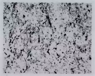
Figure 3 The metallographic structure of the surface without cracks
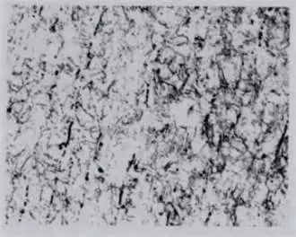
Figure 4 The metallographic structure of the surface with cracks
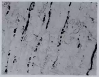
Figure 5 The black σ phase precipitated in the metallographic structure 500 x
Post URL: https://www.landeepipefitting.com/failure-causes-of-tees-in-inlet-pipelines-of-hydrocracking-pumps-part-one.html
Landee is a professional industrial pipe fitting manufacturer and be well accepted by customers all over the world, we has been producing Pipe Fitting for a variety of applications since 1985. welcome to access our website: https://www.landeepipefitting.com.
Previous: Leakages of Pipe Caps of Hot-wall Tubes of Hydrogen Conversion Furnaces (Part Two)
Next: Analysis of Failure Causes of Tees in Inlet Pipelines of Hydrocracking Pumps (Part Two)
Next: Analysis of Failure Causes of Tees in Inlet Pipelines of Hydrocracking Pumps (Part Two)
