How to Find the Lowest & Highest Points of Eccentric Reducers?
Posted: 02/09/2022 05:03:05 Hits: 100
Abstract: The eccentric reducer is a kind of pipe fitting used for changing the diameter of the pipeline, which is one of the common pipe fittings in the pipeline system. The eccentric reducer is generally used on the inlet and outlet pipes of the pump. Its main functions are to prevent cavitation and liquid. There are mainly two methods for installation. When the installation location is different, the function is also different. When installing, we must find the lowest or highest point of the eccentric reducer to install according to the installation method. We hope to improve the work efficiency and complete the installation task by finding the lowest or highest point of the eccentric reducer under the condition of ensuring a scientific basis.
1. Subject background and significance
When the pipe section is prefabricated, the pipe riveter needs to find the lowest point and the highest point of the eccentric reducer to connect with other straight pipes or accessories according to the position of the lowest point or the highest point to complete the prefabrication. However, in the process of on-site operation, I learned through understanding that the riveter generally uses his vision to judge the position of the highest point or the lowest point according to experience. During a quality inspection, a quality inspector from the Philippines questioned this kind of method and refused to accept the corresponding welding joint and appearance report, which left a deep impression on me. I want to normalize this process. Through the structural analysis of the eccentric reducer, I found that a simple measuring tool can be made, which can measure the lowest or highest point of the reducer like a ruler, so as to ensure the accuracy of the production process and the corresponding scientific basis and make our prefab more standardized and reasonable.
2. The main content
When designing a measuring tool, it is necessary to consider many practical problems, such as the deformation of the reducer, and measuring the reducer with different specifications by a measuring tool. By comprehensively considering various factors, after collecting the suggestions of experienced pipe riveters in the team, the basic shape of the measuring tool was determined; software such as CAD and PROE were used, making corresponding CAD drawings and establishing corresponding models.
2.1 CAD drawings
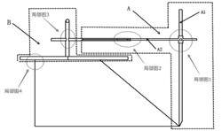
As shown in the general picture 1, the measuring tool is mainly composed of A and B. Part A is mainly used for measurement, and part B is mainly used for positioning. The lowest point or the highest point of the reducer is determined by A and B. The A1 connecting rod of A can move in the vertical direction, and its height can be controlled by adjusting the fixing screw in the detail picture 1. Therefore, it can be used to measure eccentric reducers of different lengths. In the measurement process, the lowermost part always fits the large round edge of the eccentric reducer. A2 is a connecting rod with a measuring ruler, which can move in the horizontal direction. In the measurement process, with the rotating movement of the measuring tool, the numbers change on the measuring ruler, obtaining the maximum and minimum values on the measuring tool and determining the lowest and highest points of the eccentric reducer. For details of the connection between A2 and structure B, see detailed picture 2. The connecting rod can freely retract and move within the caliper. After determining the highest point of the eccentric reducer, use the fixing screw to fix the reading of the gauge, and measure several times to ensure the accuracy of the highest point.

The general picture 1

The general picture 2
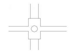
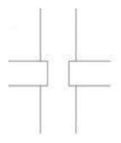
B is a base with three fixed measuring rules. The measuring rule can determine a radius according to the diameter of the small circle of the eccentric reducer, and then use this radius to find the most suitable position on the small circle of the eccentric reducer. Taking the center of the circle as the base point of rotation, the error caused by the small circle's deformation of the eccentric reducer can be eliminated. Taking the handle in the vertical direction as the center line, it is equally distributed at an included angle of 120 degrees, and the center of the small circle determined by the base can play the role of positioning. The connection between the base and the small circle is shown in the detailed picture 4. By arranging the positioning pin by slotting on the base, the reading error caused by the arc surface can be minimized. The connection between A and the handle is a flexible loop, and part A can perform a 360-degree rotational motion with the vertical handle as the baseline, as shown in the detail picture 3.
2.2 Building the model
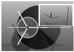
The model is shown in general picture 2. According to the size of the CAD drawing, use PROE software to build the model of the eccentric reducer. Simulate the function of the measuring tool in the model, and get the final model as shown in the general picture 2. We can intuitively see from the built model that the measuring tool fully meets the requirement of quickly and efficiently finding the highest point or the lowest point of the eccentric reducer. In general picture 2, the measuring rod of the gauge is placed exactly at the highest point of the eccentric reducer. The structural characteristics of the measuring tool can also be clearly seen through the general picture 2. The design is simple; the operation is convenient, and it can be well used in the actual construction and production to improve the construction efficiency.
Part B is a base with three fixed measuring rulers. The measuring ruler can determine a radius according to the diameter of the small circle of the eccentric reducer, and then use this radius to find the most suitable position on the small circle of the eccentric reducer. Taking the center of the circle as the base point of rotation, the error caused by the small circle deformation of the eccentric reducer can be eliminated. Taking the handle in the vertical direction as the center line, it is equally distributed at an included angle of 120 degrees, and the center of the small circle determined by the base can play the role of positioning. The connection between the base and the small circle is shown in partial Figure 4. By arranging the positioning pin by slotting on the base, the reading error caused by the arc surface can be minimized. The connection between part A and the handle is a looper structure, and part A can perform a 360-degree rotational motion with the vertical handle as the baseline, as shown in partial Figure 3.

The detail picture 1

The detail picture 2

The detail picture 3

The detail picture 4
2.2 Build the model
The model is shown in general figure 2. According to the size of the drawn CAD drawing, use PROE software to build a model of the eccentric size head, simulate the function of the measuring tool in the model, and get the final model as shown in Figure 2. We can intuitively see from the built model that the measuring tool fully meets the requirement of quickly and efficiently finding the highest point or the lowest point of the eccentric reducer. At the highest point of the eccentric reducer. The structural characteristics of the measuring tool can also be clearly seen through the small picture in the general figure 2, the design is simple, the operation is convenient, and it can be well used in the actual construction and production to improve the construction efficiency.
3. Conclusion
The design of the eccentric reducer measuring tool is introduced. A model through CAD drawings and PROE three-dimensional software are established, vividly showing the appearance and usage of the measuring tool. The eccentric reducer measuring tool can well meet the construction requirements, quickly and effectively find the lowest point or the highest point of the eccentric reducer, and solve the phenomenon of eccentric reducer on the spot, which can be used in practical operation.
2.1 CAD drawings
As shown in the general picture 1, the measuring tool is mainly composed of A and B. Part A is mainly used for measurement, and part B is mainly used for positioning. The lowest point or the highest point of the reducer is determined by A and B. The A1 connecting rod of A can move in the vertical direction, and its height can be controlled by adjusting the fixing screw in the detail picture 1. Therefore, it can be used to measure eccentric reducers of different lengths. In the measurement process, the lowermost part always fits the large round edge of the eccentric reducer. A2 is a connecting rod with a measuring ruler, which can move in the horizontal direction. In the measurement process, with the rotating movement of the measuring tool, the numbers change on the measuring ruler, obtaining the maximum and minimum values on the measuring tool and determining the lowest and highest points of the eccentric reducer. For details of the connection between A2 and structure B, see detailed picture 2. The connecting rod can freely retract and move within the caliper. After determining the highest point of the eccentric reducer, use the fixing screw to fix the reading of the gauge, and measure several times to ensure the accuracy of the highest point.

The general picture 1

The general picture 2
B is a base with three fixed measuring rules. The measuring rule can determine a radius according to the diameter of the small circle of the eccentric reducer, and then use this radius to find the most suitable position on the small circle of the eccentric reducer. Taking the center of the circle as the base point of rotation, the error caused by the small circle's deformation of the eccentric reducer can be eliminated. Taking the handle in the vertical direction as the center line, it is equally distributed at an included angle of 120 degrees, and the center of the small circle determined by the base can play the role of positioning. The connection between the base and the small circle is shown in the detailed picture 4. By arranging the positioning pin by slotting on the base, the reading error caused by the arc surface can be minimized. The connection between A and the handle is a flexible loop, and part A can perform a 360-degree rotational motion with the vertical handle as the baseline, as shown in the detail picture 3.
2.2 Building the model
The model is shown in general picture 2. According to the size of the CAD drawing, use PROE software to build the model of the eccentric reducer. Simulate the function of the measuring tool in the model, and get the final model as shown in the general picture 2. We can intuitively see from the built model that the measuring tool fully meets the requirement of quickly and efficiently finding the highest point or the lowest point of the eccentric reducer. In general picture 2, the measuring rod of the gauge is placed exactly at the highest point of the eccentric reducer. The structural characteristics of the measuring tool can also be clearly seen through the general picture 2. The design is simple; the operation is convenient, and it can be well used in the actual construction and production to improve the construction efficiency.
Part B is a base with three fixed measuring rulers. The measuring ruler can determine a radius according to the diameter of the small circle of the eccentric reducer, and then use this radius to find the most suitable position on the small circle of the eccentric reducer. Taking the center of the circle as the base point of rotation, the error caused by the small circle deformation of the eccentric reducer can be eliminated. Taking the handle in the vertical direction as the center line, it is equally distributed at an included angle of 120 degrees, and the center of the small circle determined by the base can play the role of positioning. The connection between the base and the small circle is shown in partial Figure 4. By arranging the positioning pin by slotting on the base, the reading error caused by the arc surface can be minimized. The connection between part A and the handle is a looper structure, and part A can perform a 360-degree rotational motion with the vertical handle as the baseline, as shown in partial Figure 3.

The detail picture 1

The detail picture 2

The detail picture 3

The detail picture 4
2.2 Build the model
The model is shown in general figure 2. According to the size of the drawn CAD drawing, use PROE software to build a model of the eccentric size head, simulate the function of the measuring tool in the model, and get the final model as shown in Figure 2. We can intuitively see from the built model that the measuring tool fully meets the requirement of quickly and efficiently finding the highest point or the lowest point of the eccentric reducer. At the highest point of the eccentric reducer. The structural characteristics of the measuring tool can also be clearly seen through the small picture in the general figure 2, the design is simple, the operation is convenient, and it can be well used in the actual construction and production to improve the construction efficiency.
3. Conclusion
The design of the eccentric reducer measuring tool is introduced. A model through CAD drawings and PROE three-dimensional software are established, vividly showing the appearance and usage of the measuring tool. The eccentric reducer measuring tool can well meet the construction requirements, quickly and effectively find the lowest point or the highest point of the eccentric reducer, and solve the phenomenon of eccentric reducer on the spot, which can be used in practical operation.
Post URL: https://www.landeepipefitting.com/how-to-find-the-lowest-highest-points-of-eccentric-reducers.html
Landee is a professional industrial pipe fitting manufacturer and be well accepted by customers all over the world, we has been producing Pipe Fitting for a variety of applications since 1985. welcome to access our website: https://www.landeepipefitting.com.
