Inspecting Steam Superheating Furnace Gas Collection Pipe Caps
Posted: 07/10/2023 07:38:16 Hits: 5
Abstract: The material taken from the failure part of the gas collection pipe outlet pipe cap in the radiation chamber of the steam superheating furnace was inspected for the macroscopic morphology of the corrosion part, chemical composition, inclusions, metallographic structure, oxides, scanning electron microscope observation and energy spectrum analysis. It is considered that the pipe cap is destroyed under the combined action of high-temperature steam erosion corrosion and high-temperature oxidation corrosion. The composition of the material meets the standard requirements, and the inclusion is the second phase of precipitation strengthening. The metallographic structure contains fine grain strips with a grain size of 10.5. Chromium compounds are precipitated at the grain boundaries, and the chromium is not completely dissolved into the austenite. Combined with the working conditions and heat treatment, it is considered that the solution treatment temperature of the pipe cap is too low, the time is too short, the chromium is not completely dissolved, and the grains are too small, which are the main reasons for the low strength and low oxidation resistance of the material at high temperature. The solution treatment temperature of the pipe cap should be increased, and the design of the inlet and outlet pipeline ends can also be appropriately improved.
In a petrochemical company in Jinzhou, the pipe cap of the outlet pipe of the steam superheating furnace radiation chamber of the steam superheating furnace was severely corroded and partially perforated during use, which affected the normal operation of the device. It is necessary to analyze the cause of cap failure and propose improvement measures to prevent such accidents from happening again. In this study, the materials taken from the failure part of the pipe cap were inspected on the macroscopic appearance of the corrosion part for chemical composition, inclusions, metallographic structure, oxides, scanning electron microscope observation and energy spectrum analysis.
1. The material, molding process and working conditions of the pipe cap
The material of the pipe cap is UNS N08811, and the pipe cap is an oval. The manufacturing dimensions of the pipe cap are shown in Figure 1. The pipe cap is stamped at 1000±10°C and solution treated at temperatures between 1120 to 1150°C. The pipeline operating medium is superheated steam. There are two working conditions for internal pressure, that is, negative pressure working condition of 80 to 90kPa and positive pressure working condition of 110 to 130kPa. The design operating temperature of superheated steam is that the inlet pipeline is 610°C and outlet pipeline 818°C; the actual operating temperature before shutting down is from 720 to 750°C.
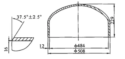
Figure 1 Manufacturing dimensions of pipe caps
2. Inspection of macroscopic appearance
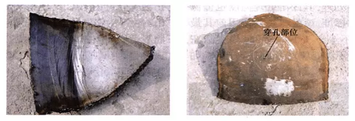
Figure 2 is the macroscopic appearance of the corroded part of the pipe cap. Judging from the sample, a circular groove is formed on the inner side of the junction between the straight edge and the folded edge of the pipe cap, and there are partial parts perforated from the outer surface. The inner oxide is blue-black and relatively dense. From the perspective of macroscopic appearance, the pipe cap is destroyed under the combined action of high-temperature steam corrosion and high-temperature oxidation corrosion. To find out the reason, it is necessary to examine whether the material meets the requirements, and whether there are problems in the manufacturing process.
3. Inspection of materials, inclusions and metallographic structure
The chemical composition analysis was carried out on the sample submitted for inspection. The results are shown in Table 1, and the material meets the standard requirements. Samples for inclusions and metallographic structures were taken from the area of greatest thinning. Figure 3 shows the typical distribution of inclusions in the sampling part. The distribution of inclusions shown in Figure 4 was observed under a scanning electron microscope. The composition analysis of points 1, 2, and 3 in the figure shows that the gray inclusions at point 1 are TiC, and the black inclusions at point 2 are SiC. Point 3 is the base. When the composition was analyzed by the scanning electron microscope, O, S, P and other impurity elements were not detected because the content was very low. Combined with the previous chemical composition analysis, although the content of the inclusions in this sample is relatively high they are all the second phase precipitation strengthening, in the form of dispersed distribution, which do not contain inclusions that endanger the strength of the material. Therefore, it is considered that the inclusions have no adverse effects on the properties of the material.
In a petrochemical company in Jinzhou, the pipe cap of the outlet pipe of the steam superheating furnace radiation chamber of the steam superheating furnace was severely corroded and partially perforated during use, which affected the normal operation of the device. It is necessary to analyze the cause of cap failure and propose improvement measures to prevent such accidents from happening again. In this study, the materials taken from the failure part of the pipe cap were inspected on the macroscopic appearance of the corrosion part for chemical composition, inclusions, metallographic structure, oxides, scanning electron microscope observation and energy spectrum analysis.
1. The material, molding process and working conditions of the pipe cap
The material of the pipe cap is UNS N08811, and the pipe cap is an oval. The manufacturing dimensions of the pipe cap are shown in Figure 1. The pipe cap is stamped at 1000±10°C and solution treated at temperatures between 1120 to 1150°C. The pipeline operating medium is superheated steam. There are two working conditions for internal pressure, that is, negative pressure working condition of 80 to 90kPa and positive pressure working condition of 110 to 130kPa. The design operating temperature of superheated steam is that the inlet pipeline is 610°C and outlet pipeline 818°C; the actual operating temperature before shutting down is from 720 to 750°C.

Figure 1 Manufacturing dimensions of pipe caps
2. Inspection of macroscopic appearance
Figure 2 is the macroscopic appearance of the corroded part of the pipe cap. Judging from the sample, a circular groove is formed on the inner side of the junction between the straight edge and the folded edge of the pipe cap, and there are partial parts perforated from the outer surface. The inner oxide is blue-black and relatively dense. From the perspective of macroscopic appearance, the pipe cap is destroyed under the combined action of high-temperature steam corrosion and high-temperature oxidation corrosion. To find out the reason, it is necessary to examine whether the material meets the requirements, and whether there are problems in the manufacturing process.
3. Inspection of materials, inclusions and metallographic structure
The chemical composition analysis was carried out on the sample submitted for inspection. The results are shown in Table 1, and the material meets the standard requirements. Samples for inclusions and metallographic structures were taken from the area of greatest thinning. Figure 3 shows the typical distribution of inclusions in the sampling part. The distribution of inclusions shown in Figure 4 was observed under a scanning electron microscope. The composition analysis of points 1, 2, and 3 in the figure shows that the gray inclusions at point 1 are TiC, and the black inclusions at point 2 are SiC. Point 3 is the base. When the composition was analyzed by the scanning electron microscope, O, S, P and other impurity elements were not detected because the content was very low. Combined with the previous chemical composition analysis, although the content of the inclusions in this sample is relatively high they are all the second phase precipitation strengthening, in the form of dispersed distribution, which do not contain inclusions that endanger the strength of the material. Therefore, it is considered that the inclusions have no adverse effects on the properties of the material.

(a) The erosion groove inside the pipe cap (b) The perforation position on the outer surface of the pipe cap
Figure 2 Macro morphology of corrosion parts of the corroded part of the pipe cap
Table 1 Chemical composition of the sample
Table 1 Chemical composition of the sample
| Alloy composition | UNS N08811 | Testing values |
| C | 0.06 to 0. 10 | 0.080 |
| Cr | 19.0 to 23.0 | 20.26 |
| Ni | 30.0 to 35.0 | 31.13 |
| Cu | Less than and equal to 0.75 | 0.035 |
| Al | 0. 15 to 0. 60 | 0.49 |
| Ti | 0. 15 to 0. 60 | 0.505 |
| Si | Less than and equal to 1.00 | 0. 27 |
| Mn | Less than and equal to 1.50 | 0.96 |
| S | Less than and equal to 0.015 | 0.001 |
| P | 0.019 |
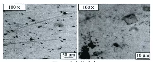
Figure 3 Distribution of impurities
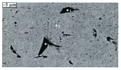
Figure 4 The SEM photo of impurities
The metallographic structure is shown in Figures 5 and 6. After observing the metallographic structure of the material, it is found that the grains of the material are very uneven, and there are fine grain strips which are parallel to the rolling direction. The average grain size of the coarse grain area is 3.5; the welding seam heat affected zone 6, and the fine grain strip area 10.5. It is found that along the thickness direction of the plate, there are up to 4 fine-grained bands. Very fine grained regions weaken the strength of the material at high temperatures. According to ASTM B409 standard, the average grain size of UNS N08811 in the annealed state should be grade 5 or coarser. The grain size of the fine-grained strip region does not meet the requirements of the standard.
The inclusions are distributed in the grain boundary and the grain, most of which are in the form of diffuse distribution, and there are also inclusions in the form of stripes. These inclusions are precipitation strengthening phases, which have a strengthening effect on the matrix material. Observing the notch morphology at the edge shows that the cracks are intergranular cracks, indicating that the failure process is a process of exfoliation of grains one by one, and the intragranular strength of the grains is higher than the grain boundary strength. The structure of the welding seam is coarse, and various alloy compounds are also precipitated in the grain and at the grain boundary. However, from the appearance and morphology, the welding seam is more resistant to corrosion caused by scouring than the matrix. From the extension path of the groove in Figure 5(C), it can be inferred that the fine-grain strip seems to help the groove to expand inward, because the grains around the fine-grain strip are also relatively small, and the smaller the grain is, the more active the grain boundary become; the easier it is to corrode and the lower the strength is. When observing the metallography, it was found that there was a repair surfacing welding seam at the junction of the flange and the straight edge of the pipe cap. There may be a lack of metal due to some reasons in the forming process, and surfacing and grinding were carried out afterward.
In the process of hot stamping caps, the material may not be easily deformed due to the low partial temperature of the outer surface, and the high speed of hot punching may cause scratches on the outer surface of the pipe cap, resulting in "lack of metal". There are fine-grained bands in the base metal on both sides of the welding seam, indicating that the fine-grained bands are formed in the rolling process of the original rolled plate, not formed in the hot stamping process. If the rolled plate is required to be supplied in the solution treatment state, the heat preservation time in the solution treatment process is insufficient; the solution treatment temperature is low; the banded structure formed in the rolling process is not eliminated, and the alloying elements are not completely dissolved into the matrix structure. This leads to the formation of more second phases at the grain boundaries, making it difficult for the grains to grow. After the hot stamping of the pipe cap, the folded side of the pipe cap should be fully solution treated before welding with the straight side, and the solution treatment temperature is also low. according to the ASTM B409 standard, the final heat treatment temperature of the material before putting into use should not be less than 1149°C, and it is solution treated at 1120 to 1150°C. Otherwise, the grains will not be too fine.
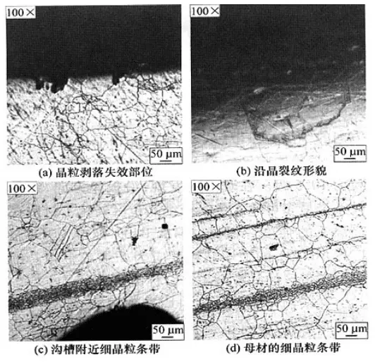
(a) Grain peeling failure site (b) Intergranular crack morphology
(c) Fine grain band near the groove (d) Fine-grained strips of base metal
Figure 5 Metallographic structure of base metal in different parts
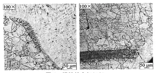
Figure 6 Metallographic structure of the welding seam
Post URL: https://www.landeepipefitting.com/inspecting-steam-superheating-furnace-gas-collection-pipe-caps.html
Landee is a professional industrial pipe fitting manufacturer and be well accepted by customers all over the world, we has been producing Pipe Fitting for a variety of applications since 1985. welcome to access our website: https://www.landeepipefitting.com.
Previous: Carbon Steel Pipe Fittings
Next: Reasons & Countermeasures for Steam Superheating Furnace Gas Collection Pipe Caps
Next: Reasons & Countermeasures for Steam Superheating Furnace Gas Collection Pipe Caps
