Measures for Temperature Rise of the Fire Pipe Unions (Part One)
Posted: 09/12/2023 03:32:41 Hits: 13
Abstract: The fire protection system of a hydropower station mainly consists of a gas fire extinguishing system, a water spray fire extinguishing system, and a fire monitoring and alarm system. The fire protection system of a hydropower station plays a very important role in ensuring the safe and stable operation of the entire hydropower station, especially the water spray areas such as unit fire protection and main transformer fire protection. It must be ensured that its equipment is intact and reliable and can be put into use when a fire occurs. The temperature of the fire protection pipe joints of the power station unit increased abnormally during operation, which seriously affected the safe and stable operation of the unit. The reasons for the abnormal increase in temperature of fire ring pipe joints are analyzed in detail and the corresponding treatment measures are taken.
Introduction
This hydropower station is located in Sichuan, with a total of 4 mixed-flow turbine generator units arranged in the underground factory, with an installed capacity of one million kilowatts. The fire protection system of the power station mainly includes fire hydrants, fire extinguishers and other fire protection equipment systems, underground auxiliary factory IG541 pipeline gas fire extinguishing systems, outlet shaft high-pressure water mist fire extinguishing systems, switch station IG541 pipeline gas fire extinguishing systems, fire extinguishing systems, water spray systems and fire monitoring systems.
(1) Fire hydrants, fire extinguishers and other fire-fighting equipment systems: There are fire hydrant water supply systems on each floor of the main factory, auxiliary factory and main transformer tunnel. It is a normal high-pressure water supply system. Fire hydrants on the upper floors of the generator adopt pressure-reducing and stabilizing fire hydrants. There are fire hydrant water supply systems on each floor of the switch station indoors and outdoors, which are temporary high-pressure water supply systems. Fire water supply equipment is installed in the fire water pump room on the first floor. Fire extinguishers are installed on each floor of the main powerhouse, auxiliary powerhouse, main transformer tunnel, switch station, traffic cavern and some equipment rooms. Fire-fighting equipment is installed in various cable channels, cable rooms, oil tank rooms, central control rooms and relay protection rooms in the factory area.
(2) IG541 pipeline gas fire extinguishing system in the underground auxiliary factory: The IG541 gas fire extinguishing system is installed in the central control room and computer room at the elevation of 2002.20m in the underground auxiliary factory and the communication equipment room and mobile and telecommunications room at the elevation of 1997.20m. The gas cylinder room is located at 2007.80 m elevation.
(3) High-pressure water mist fire extinguishing system in the outlet shaft: A high-pressure water mist fire extinguishing system is installed in the 500kV cable well and low-voltage cable well in the outlet shaft of the underground factory. The two cable wells share a system, each of which is a protection zone. Each protective area is equipped with an open single-valve box. The high-pressure water mist pump unit and water tank are installed in the high-pressure water mist pump room at an altitude of 1992.00m in the main transformer tunnel.
(4) Switch station IG541 pipeline gas fire extinguishing system: The IG541 gas fire extinguishing system is installed in the communication equipment room at an altitude of 2108.15m and the relay protection room at an altitude of 2117.85m in the relay protection building of the switch station. The gas cylinder room is located at an altitude of 2108.15m.
(5) Water spray systems: The main transformer is equipped with a main transformer water spray fire extinguishing system, and the deluge valve group is arranged in the deluge valve chamber on the main transformer floor. The generator is equipped with a water spray fire extinguishing system, and the deluge valve is arranged on the turbine floor. The reactor is equipped with a water spray fire extinguishing system, and the water pump and deluge valve group are arranged in the reactor water spray equipment room at an altitude of 2102.15m in the switch station.
(6) Fire monitoring systems: The system consists of centralized fire alarm control systems (host) set up in the central control rooms, regional fire alarm control systems set up in each area of the factory, fire linkage control equipment, fire broadcasting equipment, and fire telephone hosts and various detectors, manual alarm buttons, fire hydrant buttons, control modules, signal modules, fire broadcast speakers, sound and light alarms and fire telephones.
1. Design and layout of fire-fighting water spray extinguishing systems for generating units
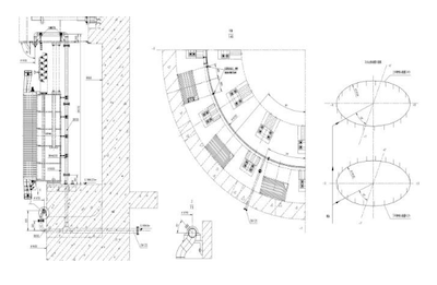
The water source for generator water spray fire extinguishing is drawn from the DN200 fire hydrant water supply ring pipe on the 1986.00m floor of the main factory building. The water pressure in the ring pipe is about 0.8MPa. The fire extinguishing water volume of the generator is 150m3/h. A deluge valve of DN150 is installed on the fire water supply pipe of each generator, and two fire extinguishing ring pipes are installed on the upper and lower floors of the machine pit. There is one upper ring pipe with 24 nozzles, and one lower ring pipe with 24 nozzles. The layout is shown in Figure 1. All steel pipes and joints are made from stainless steel, formed and pre-assembled in the factory, and the closest discharge distance to the stator coil is not less than 160mm. The working pressure of the fire extinguishing water pipe is 0.45 to 0.6MPa, and the intensity of the spray water volume is not less than 10L/min. When a fire occurs, the fire detector installed in the generator windshield can send a signal, and the deluge valve can be opened automatically or manually on site to realize the generator water spray fire extinguishing.

Figure 1 The layout of the generator fire protection pipe
2. Abnormal temperature and hazards of the fire ring pipe joints of the generator set
2.1 Phenomenon
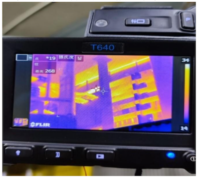
The hydropower station's turbine generator unit was installed and put into operation in October 2021. An inspection in October 2021 found that the temperature of the joint at the neutral point of the upper ring pipe of the generator fire ring pipe of Unit 3 was abnormal, and the actual measured temperature was 268°. At this time, the unit load is approximately 1500MW. The maximum temperature of the stator coil is less than 60°; the maximum temperature of the stator core is less than 50°, and the maximum temperature of the air cooler hot air is less than 40°. This also exists when inspecting and measuring other joints and units.

Figure 2 The photo of the temperature measurement of the joint before maintenance
2.2 Hazards
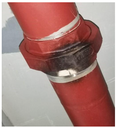
As can be seen from Figure 3, abnormal joint temperature will cause the joints and gaskets to age quickly and be damaged, resulting in loose sealing. If the temperature continues to rise, it may even cause the joints to deform and melt. Once a fire breaks out in the generator stator core, the generator fire water spray fire extinguishing system will not be able to effectively extinguish the fire.

Figure 3 Photo of the joint turning black when the temperature is too high.
Introduction
This hydropower station is located in Sichuan, with a total of 4 mixed-flow turbine generator units arranged in the underground factory, with an installed capacity of one million kilowatts. The fire protection system of the power station mainly includes fire hydrants, fire extinguishers and other fire protection equipment systems, underground auxiliary factory IG541 pipeline gas fire extinguishing systems, outlet shaft high-pressure water mist fire extinguishing systems, switch station IG541 pipeline gas fire extinguishing systems, fire extinguishing systems, water spray systems and fire monitoring systems.
(1) Fire hydrants, fire extinguishers and other fire-fighting equipment systems: There are fire hydrant water supply systems on each floor of the main factory, auxiliary factory and main transformer tunnel. It is a normal high-pressure water supply system. Fire hydrants on the upper floors of the generator adopt pressure-reducing and stabilizing fire hydrants. There are fire hydrant water supply systems on each floor of the switch station indoors and outdoors, which are temporary high-pressure water supply systems. Fire water supply equipment is installed in the fire water pump room on the first floor. Fire extinguishers are installed on each floor of the main powerhouse, auxiliary powerhouse, main transformer tunnel, switch station, traffic cavern and some equipment rooms. Fire-fighting equipment is installed in various cable channels, cable rooms, oil tank rooms, central control rooms and relay protection rooms in the factory area.
(2) IG541 pipeline gas fire extinguishing system in the underground auxiliary factory: The IG541 gas fire extinguishing system is installed in the central control room and computer room at the elevation of 2002.20m in the underground auxiliary factory and the communication equipment room and mobile and telecommunications room at the elevation of 1997.20m. The gas cylinder room is located at 2007.80 m elevation.
(3) High-pressure water mist fire extinguishing system in the outlet shaft: A high-pressure water mist fire extinguishing system is installed in the 500kV cable well and low-voltage cable well in the outlet shaft of the underground factory. The two cable wells share a system, each of which is a protection zone. Each protective area is equipped with an open single-valve box. The high-pressure water mist pump unit and water tank are installed in the high-pressure water mist pump room at an altitude of 1992.00m in the main transformer tunnel.
(4) Switch station IG541 pipeline gas fire extinguishing system: The IG541 gas fire extinguishing system is installed in the communication equipment room at an altitude of 2108.15m and the relay protection room at an altitude of 2117.85m in the relay protection building of the switch station. The gas cylinder room is located at an altitude of 2108.15m.
(5) Water spray systems: The main transformer is equipped with a main transformer water spray fire extinguishing system, and the deluge valve group is arranged in the deluge valve chamber on the main transformer floor. The generator is equipped with a water spray fire extinguishing system, and the deluge valve is arranged on the turbine floor. The reactor is equipped with a water spray fire extinguishing system, and the water pump and deluge valve group are arranged in the reactor water spray equipment room at an altitude of 2102.15m in the switch station.
(6) Fire monitoring systems: The system consists of centralized fire alarm control systems (host) set up in the central control rooms, regional fire alarm control systems set up in each area of the factory, fire linkage control equipment, fire broadcasting equipment, and fire telephone hosts and various detectors, manual alarm buttons, fire hydrant buttons, control modules, signal modules, fire broadcast speakers, sound and light alarms and fire telephones.
1. Design and layout of fire-fighting water spray extinguishing systems for generating units
The water source for generator water spray fire extinguishing is drawn from the DN200 fire hydrant water supply ring pipe on the 1986.00m floor of the main factory building. The water pressure in the ring pipe is about 0.8MPa. The fire extinguishing water volume of the generator is 150m3/h. A deluge valve of DN150 is installed on the fire water supply pipe of each generator, and two fire extinguishing ring pipes are installed on the upper and lower floors of the machine pit. There is one upper ring pipe with 24 nozzles, and one lower ring pipe with 24 nozzles. The layout is shown in Figure 1. All steel pipes and joints are made from stainless steel, formed and pre-assembled in the factory, and the closest discharge distance to the stator coil is not less than 160mm. The working pressure of the fire extinguishing water pipe is 0.45 to 0.6MPa, and the intensity of the spray water volume is not less than 10L/min. When a fire occurs, the fire detector installed in the generator windshield can send a signal, and the deluge valve can be opened automatically or manually on site to realize the generator water spray fire extinguishing.

Figure 1 The layout of the generator fire protection pipe
2. Abnormal temperature and hazards of the fire ring pipe joints of the generator set
2.1 Phenomenon
The hydropower station's turbine generator unit was installed and put into operation in October 2021. An inspection in October 2021 found that the temperature of the joint at the neutral point of the upper ring pipe of the generator fire ring pipe of Unit 3 was abnormal, and the actual measured temperature was 268°. At this time, the unit load is approximately 1500MW. The maximum temperature of the stator coil is less than 60°; the maximum temperature of the stator core is less than 50°, and the maximum temperature of the air cooler hot air is less than 40°. This also exists when inspecting and measuring other joints and units.

Figure 2 The photo of the temperature measurement of the joint before maintenance
2.2 Hazards
As can be seen from Figure 3, abnormal joint temperature will cause the joints and gaskets to age quickly and be damaged, resulting in loose sealing. If the temperature continues to rise, it may even cause the joints to deform and melt. Once a fire breaks out in the generator stator core, the generator fire water spray fire extinguishing system will not be able to effectively extinguish the fire.

Figure 3 Photo of the joint turning black when the temperature is too high.
Post URL: https://www.landeepipefitting.com/measures-for-temperature-rise-of-the-fire-pipe-unions-part-one.html
Landee is a professional industrial pipe fitting manufacturer and be well accepted by customers all over the world, we has been producing Pipe Fitting for a variety of applications since 1985. welcome to access our website: https://www.landeepipefitting.com.
Previous: Inspection of Hydrogen Pipelines in Refining and Chemical Hydrogen Production Units
Next: Measures for Temperature Rise of the Fire Pipe Unions (Part Two)
Next: Measures for Temperature Rise of the Fire Pipe Unions (Part Two)
