Optimal Design of Expansion Joints in High-Temperature Flue Gas Pipes
Posted: 10/15/2024 09:41:10 Hits: 25
On this page
3. Analysis of Stable Failure Causes
According to the characteristics of failure in expansion joints, instability deformation mainly occurs due to the forces from the blind plate and shaft displacement. The factors causing instability in expansion joints are primarily defects in the joints themselves, changes in medium working conditions, and unreasonable arrangements of pipeline supports. The expansion joint of this device's flue gas pipeline bellows has not been repaired and functioned well during previous operations. The condition of the expansion joint shows no signs of defects. Therefore, the issue of defects in the expansion joint can be ruled out first, with the subsequent focus on the research and analysis of the medium and pipeline supports.
3.1 Analysis of Medium Working Conditions
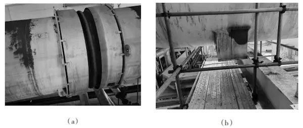
After comparing the online monitoring records, it was found that when the flue gas pipeline deformed, the pipeline butterfly valve M1, M2 also experienced jamming at the small opening position, resulting in increased pressure in the pipeline. The maximum pressure reached 0.25MPa, significantly exceeding the normal working pressure. Although the valve returned to normal after treatment, the pipeline expansion joint had already deformed due to the high pressure. According to calculations, when the pressure is 0.25MPa, the internal pressure from the blind plate force of the bellows expansion joint reaches 35 times the normal operating level. The immense blind plate force acts on both the expansion joint and the fixed support, causing the fixed support to fail and displace, as well as the expansion joint to stretch and deform, as shown in Figure 4.


Figure 4 Stretching of expansion joint of pipeline and displacement of pipe support
The design parameters of the expansion joint are queried: the design pressure is 0.26MPa; the design axial displacement is 45 mm, and the axial displacement of the pipeline is mainly due to linear expansion caused by temperature; the pipeline elongation calculation formula is as follows:
Where a is the average expansion coefficient of steel at the applicable temperature (°C), L is the flue length (mm), and ΔT is the temperature difference (°C). The temperature difference of the pipeline is defined as the difference between the ambient temperature during installation and the temperature of the pipeline's metal material under working conditions, with a maximum value of 150°C. The linear expansion coefficient of carbon steel is α = 11.88 × 10⁻⁶ °C⁻¹. Using the above formula, the thermal displacement of the pipeline can be calculated based on the length of the pipeline affected by each expansion joint, as shown in Table 1. The allowable axial displacement of the expansion joint in each section of the flue gas pipeline exceeds the thermal elongation of the pipeline. Therefore, the axial displacement caused by the operating temperature is considered a normal condition and is not the main cause of expansion joint instability.
Table 1 Comparison of allowable axial displacement of expansion joints and thermal expansion of pipelines
| Expansion Joint | Pipeline Length (m) | Allowable Axial Displacement (mm) | Thermal Elongation (mm) | Conclusion |
| 1# | 22 | 45 | 39.2 | Qualified |
| 2# | 15 | 35 | 26.7 | Qualified |
| 3# | 15 | 50 | 26.7 | Qualified |
3.2 Pipeline Support Analysis
By comparing Figure 1 and Figure 2, it is evident that after the flue gas pipeline inspection and reconstruction, the straight pipe section's support has not changed; the tee’s branch pipe has been cut indiscriminately, and the fixed support after the tee does not effectively stabilize the straight pipe section. The length of the pipeline between the S1 and S5 fixed supports is 33 m, and two single axial expansion joints have been installed. There is no fixed support between the expansion joints to absorb the internal pressure blind plate force of the pipeline, which reduces pipeline stability and fails to meet thermal expansion requirements after the inspection and reconstruction. After the pipeline was put into use and heated, it twisted and deformed due to expansion displacement and blind plate force, resulting in tensile instability of expansion joints 1 and 2. While deforming, the pipeline generated significant thrust in the axial direction, with the displacement inertia force and blind plate force simultaneously acting on the far-end fixed support, causing it to fail and aggravating pipeline displacement. Due to the presence of fixed supports on both sides of joint 3, no significant twisting occurred; however, a minor extension was observed with the pipeline's axial displacement. In summary, during the commissioning of the flue gas pipeline, valve failure caused increased pressure, which directly led to the stable failure of both the pipeline and the expansion joint. Analysis indicates that changes in the pipeline process and mismatches between the pipeline support arrangement and the new process were the root causes of the failure.
4. Design Optimization and Transformation of Expansion Joint Pipelines
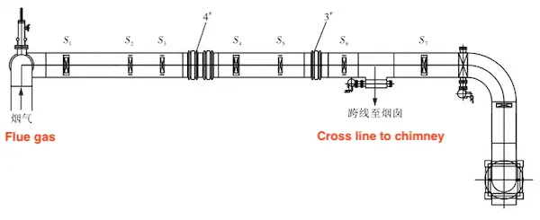
Eliminate potential failure risks of the flue gas pipeline and expansion joint by re-inspecting, redesigning, and optimizing the pipeline (Figure 5). On one hand, the severely failed 1# and 2# expansion joints were removed and replaced with idle expansion joints; on the other hand, the stability issue of the pipeline was resolved. On the pipeline where the free expansion joint was installed, the upstream and downstream elbows of the expansion joint, the diameter change in the straight pipe section, the tee, the valve connection between the two expansion joints, and the blind end of the pipeline should all be equipped with intermediate and main fixed frames. Only one axial free expansion should be positioned between the two fixed supports. The distance between the first guide support and the expansion joint should not exceed 4D, and the distance between the second guide support and the first guide support should not exceed 14D. The maximum distance between the remaining supports should be determined based on the provisions of the pipeline span. Additionally, S4 is converted into a fixed support, and the bearing strength of S1 and S7 fixed supports is simultaneously increased.

Figure 5 Optimized design layout of flue gas pipeline
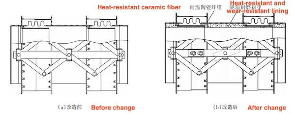
The replacement expansion joint is a proportional connecting rod compound free-expansion joint. The original design lacks temperature resistance, and the axial displacement is only 30 mm. Directly replacing the 1# and 2# expansion joints does not accommodate the pipeline's thermal displacement and cannot withstand the working conditions of high-temperature flue gas, so on-site modification is required. First, the internal construction of the expansion joint was performed in accordance with the requirements of GB/T 50474-2008, "Technical Specifications for Heat Insulation and Wear-Resistant Lining," and heat insulation and wear-resistant lining were added. The gap between the guide tube and the bellows was filled with heat-resistant ceramic fiber materials to reduce the direct impact of high-temperature flue gas on the bellows.
Second, the key modification was to increase the allowable axial displacement of the expansion joint. After communication and research with the manufacturer, it was determined that the allowable axial displacement of the expansion joint could be increased, and the limit hole of the connecting rod hinge mechanism needed to be expanded and modified. The hinge mechanism of the expansion joint is relatively complex (Figure 6(a)), and modifying the limit hole is difficult, time-consuming, and labor-intensive. Therefore, it was decided to modify the connecting rod directly. The connecting rod was cut in the middle, high-strength bolts were welded to the two short heads, and a middle connecting plate with sufficient strength was reinstalled. Limit holes were added to the plate, and the original connecting rod was reconnected using bolts. The allowable axial displacement of the expansion joint was increased to 80 mm through the limit holes on the connecting plate to ensure its normal operation. After the modification, as shown in Figure 6(b), the modification efficiency was greatly improved, and the maintenance time was shortened.

Figure 6 Expansion amount and temperature resistance renovation of the expansion joint

Figure 5 Optimized design layout of flue gas pipeline
The replacement expansion joint is a proportional connecting rod compound free-expansion joint. The original design lacks temperature resistance, and the axial displacement is only 30 mm. Directly replacing the 1# and 2# expansion joints does not accommodate the pipeline's thermal displacement and cannot withstand the working conditions of high-temperature flue gas, so on-site modification is required. First, the internal construction of the expansion joint was performed in accordance with the requirements of GB/T 50474-2008, "Technical Specifications for Heat Insulation and Wear-Resistant Lining," and heat insulation and wear-resistant lining were added. The gap between the guide tube and the bellows was filled with heat-resistant ceramic fiber materials to reduce the direct impact of high-temperature flue gas on the bellows.
Second, the key modification was to increase the allowable axial displacement of the expansion joint. After communication and research with the manufacturer, it was determined that the allowable axial displacement of the expansion joint could be increased, and the limit hole of the connecting rod hinge mechanism needed to be expanded and modified. The hinge mechanism of the expansion joint is relatively complex (Figure 6(a)), and modifying the limit hole is difficult, time-consuming, and labor-intensive. Therefore, it was decided to modify the connecting rod directly. The connecting rod was cut in the middle, high-strength bolts were welded to the two short heads, and a middle connecting plate with sufficient strength was reinstalled. Limit holes were added to the plate, and the original connecting rod was reconnected using bolts. The allowable axial displacement of the expansion joint was increased to 80 mm through the limit holes on the connecting plate to ensure its normal operation. After the modification, as shown in Figure 6(b), the modification efficiency was greatly improved, and the maintenance time was shortened.

Figure 6 Expansion amount and temperature resistance renovation of the expansion joint
5. Conclusion
(1) The main cause of the consistent failure of the expansion joint in the high-temperature flue gas pipeline is the improper arrangement of the pipeline support. By optimizing and modifying the expansion joint pipeline system, adding fixed supports, reinforcing the guide supports, and replacing defective expansion joints, the failure issue in the flue gas pipeline was successfully resolved.
(2) In a pipeline system using expansion joints, the selection, arrangement, and load-bearing capacity of the supports are crucial to the stability of the pipeline. The stability of pipeline operations is also critical to ensuring the safe functioning of the pipeline.
(3) When designing and selecting pipeline supports, fixed supports should be installed on both sides of each free-type expansion joint, and these supports must withstand the effects of axial internal pressure, bellows elastic force, and friction force under maximum working conditions. Additionally, the influence of other forces, such as wind load, on the supports should be considered to ensure the overall stability of the pipeline.
Post URL: https://www.landeepipefitting.com/optimal-design-of-expansion-joints-in-high-temperature-flue-gas-pipes.html
Landee is a professional industrial pipe fitting manufacturer and be well accepted by customers all over the world, we has been producing Pipe Fitting for a variety of applications since 1985. welcome to access our website: https://www.landeepipefitting.com.
Previous: Application & Failure of Expansion Joints in High-Temperature Flue Gas Pipes
Next: Applications of Electrodeposition Technology to the Inner Walls of Pipe Fittings
Next: Applications of Electrodeposition Technology to the Inner Walls of Pipe Fittings
