Pictographic Anode for Pipe Fittings
Posted: 11/07/2024 04:34:22 Hits: 7
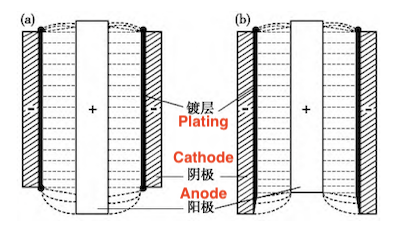
Faraday's law indicates that the uniformity of the cathode surface coating during electrodeposition is closely related to the average current density at each location on the cathode. During electrodeposition on the inner wall of a complex-shaped pipe fitting, using only a regular-shaped inner anode or an inappropriately shaped inner anode can cause uneven current density distribution on the cathode surface, affecting coating uniformity and structural performance. Pictographic anodes are typically used to address the issue of uneven coating on complex-shaped cathode surfaces. A "pictographic anode" refers to an anode shape similar to the cathode surface, which is sometimes called a profiling anode. Pictographic anodes come in two structural forms: integral and combined. Currently, pictographic anodes are widely used in electrodeposition. Hongbo Xie and others used a tapered, four-pointed star-shaped inner anode to solve uneven hard chromium coating issues on the inner corners and upper and lower ends of a square pipe fitting's inner wall. Jianming Yang and others designed a new combined pictographic anode that enabled the electroforming of complex rotating parts, achieving an evenly distributed electroforming layer thickness and alloy composition. However, due to a lack of precise design methods for pictographic anode contours, these anodes were often selected based on experience or on-site adjustments, resulting in only moderate effectiveness. To replace traditional empirical methods, Jianming Yang and others used numerical simulations to refine the pictographic anode shape through electric field analysis and optimization, improving current density uniformity across the cathode surface. Guopeng Ren and others used ANSYS finite element analysis software to simulate and determine that when the distance between the cathode and anode is constant, electric field strength and distribution vary significantly at the R corner and surrounding areas of the crystallizer’s inner surface, allowing them to identify the optimal anode shape for chromium electroplating. While the pictographic anode improves electric field distribution on the cathode surface, edge and tip effects during electrodeposition can cause uneven electric field distribution in the cathode's center and corner areas, impacting overall coating uniformity, as shown in Figure 1. When one end of the inner anode is too long, dense electric field lines on the corresponding cathode end result in a thicker coating and a "dog bone" shape (Figure 1a). Conversely, if one end of the inner anode is too short, sparse electric field lines lead to a thinner coating (Figure 1b).

Figure 1 The effect of inner anode size on the uniformity of electroplating electric field and coating thickness: (a) inner anode too long, leading to thicker coating (b) inner anode too short, resulting in thinner coating at the bottom
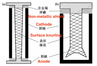
Therefore, improving the pictographic anode design or adjusting the electric field distribution through auxiliary means (such as insulation shielding, auxiliary cathodes, or auxiliary anodes) is necessary based on the specific geometric characteristics of the cathode. Based on these requirements, two typical inner anodes for pipe electrodeposition are designed, as shown in Figure 2. For long pipelines in vertical electrodeposition, the inner anode is designed as an I-shaped structure, with a slightly larger diameter at the upper end than the lower end to improve coating thickness distribution between the upper and lower ends (Figure 2a). A non-metallic shielding block is added where it contacts the cathode tube to prevent electric line concentration at both ends. For horizontal electrodeposition, the inner anode is designed as a T-shaped structure. Additionally, the anode surface that is flush with the cathode is knurled to increase surface area and prevent passivation. For semi-enclosed pipes or containers, a T-shaped inner anode is used (Figure 2b). This design also incorporates surface knurling and non-metallic shielding. However, electric lines near the inner corners of the pipe are usually sparse, leading to a thin coating and even leakage. To address this, a pointed finger-shaped auxiliary anode is used to increase current density at the inner corner through the tip discharge effect, thereby enhancing coating uniformity.

Figure 2 Typical inner anode designs for electrodeposition of pipe fittings: (a) a long pipe (b) a semi-enclosed pipe or container
Once the configuration of the pipe fitting and the inner anode is determined, the distance between the cathode and the anode becomes an important factor in determining the distribution of the electrodeposited coating on the cathode surface. Studies have shown that in the electrodeposition process, an optimal distance exists between the cathode and the anode, and distances that are too large or too small reduce the uniformity of the coating. In electrodeposition on the inner wall of the pipe, when the distance between the cathode and anode is small, the inner anode diameter is relatively large. Consequently, less plating solution flows through the tube cross-section per unit time, leading to an insufficient ion supply and low electrodeposition efficiency. If the distance is large, although the electric field distribution is relatively uniform, there is a significant difference in the cathode and anode areas, making the anode prone to passivation. To obtain the optimal cathode-anode spacing, numerical simulation technology can be used and verified, then further optimized through experiments. Reports indicate that when the inner wall of the oil cylinder is flow-plated with a Cu-Sn alloy, optimal coating quality is achieved at a cathode-anode spacing of 5 nm.


Figure 1 The effect of inner anode size on the uniformity of electroplating electric field and coating thickness: (a) inner anode too long, leading to thicker coating (b) inner anode too short, resulting in thinner coating at the bottom
Therefore, improving the pictographic anode design or adjusting the electric field distribution through auxiliary means (such as insulation shielding, auxiliary cathodes, or auxiliary anodes) is necessary based on the specific geometric characteristics of the cathode. Based on these requirements, two typical inner anodes for pipe electrodeposition are designed, as shown in Figure 2. For long pipelines in vertical electrodeposition, the inner anode is designed as an I-shaped structure, with a slightly larger diameter at the upper end than the lower end to improve coating thickness distribution between the upper and lower ends (Figure 2a). A non-metallic shielding block is added where it contacts the cathode tube to prevent electric line concentration at both ends. For horizontal electrodeposition, the inner anode is designed as a T-shaped structure. Additionally, the anode surface that is flush with the cathode is knurled to increase surface area and prevent passivation. For semi-enclosed pipes or containers, a T-shaped inner anode is used (Figure 2b). This design also incorporates surface knurling and non-metallic shielding. However, electric lines near the inner corners of the pipe are usually sparse, leading to a thin coating and even leakage. To address this, a pointed finger-shaped auxiliary anode is used to increase current density at the inner corner through the tip discharge effect, thereby enhancing coating uniformity.

Figure 2 Typical inner anode designs for electrodeposition of pipe fittings: (a) a long pipe (b) a semi-enclosed pipe or container
Once the configuration of the pipe fitting and the inner anode is determined, the distance between the cathode and the anode becomes an important factor in determining the distribution of the electrodeposited coating on the cathode surface. Studies have shown that in the electrodeposition process, an optimal distance exists between the cathode and the anode, and distances that are too large or too small reduce the uniformity of the coating. In electrodeposition on the inner wall of the pipe, when the distance between the cathode and anode is small, the inner anode diameter is relatively large. Consequently, less plating solution flows through the tube cross-section per unit time, leading to an insufficient ion supply and low electrodeposition efficiency. If the distance is large, although the electric field distribution is relatively uniform, there is a significant difference in the cathode and anode areas, making the anode prone to passivation. To obtain the optimal cathode-anode spacing, numerical simulation technology can be used and verified, then further optimized through experiments. Reports indicate that when the inner wall of the oil cylinder is flow-plated with a Cu-Sn alloy, optimal coating quality is achieved at a cathode-anode spacing of 5 nm.

Post URL: https://www.landeepipefitting.com/pictographic-anode-for-pipe-fittings.html
Landee is a professional industrial pipe fitting manufacturer and be well accepted by customers all over the world, we has been producing Pipe Fitting for a variety of applications since 1985. welcome to access our website: https://www.landeepipefitting.com.
Previous: Stress Analysis of High-Temperature Steam Pipe Reducers Under Service Conditions
Next: Factors Affecting Electrodeposition on the Inner Wall of Pipe Fittings
Next: Factors Affecting Electrodeposition on the Inner Wall of Pipe Fittings
