Stress Analysis of High-Temperature Steam Pipe Reducers Under Service Conditions
Posted: 09/04/2024 06:41:10 Hits: 22
1. Stress Analysis of Reducers Under Theoretical Load Conditions
To verify the accuracy of the calculation model, a finite element stress analysis of the reducers under theoretical load conditions was first carried out. The outer diameter of the reducer’s bigger end was selected as 406.4 mm × 30 mm, and the outer diameter of the small-end pipe was selected as 353 mm × 24 mm; the material was A335 P91. The structure of the reducer is shown in Figure 1, where OD1 is the outer diameter of the large end, OD2 is the outer diameter of the small end; L1 is the length of the straight pipe section at the large end, L1 = 100 mm; L2 is the length of the variable diameter section, L2 = 150 mm; L3 is the length of the straight pipe section at the small end, L3 = 100 mm.
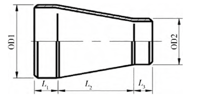
Figure 1 Reducer structure
Assuming the analysis state is at the design temperature of 574.9℃, under this condition, the material elastic modulus E = 167.5 GPa and Poisson's ratio v = 0.3. The calculation adopts the linear elastic constitutive model to analyze the influence of different external loads on the stress of the reducer. The stress distribution characteristics of the reducer under internal pressure, tension, bending moment, and torque are studied separately.
Table 1 External loads of various working conditions
| Internal pressure/MPa | Tension/N | Bending moment/Nm | Torque/Nm |
| 10.4 | 1 × 10⁶ | 1 × 10⁵ | 1 × 10⁵ |
According to the characteristics of external loads, the structural stress distribution is symmetrical in the circumferential direction under the action of internal pressure, tension, and torque. Under the action of the bending moment, the structural stress on both sides of the neutral plane of the pipeline in the XZ direction is symmetrically distributed (Figure 2). To better study the stress distribution characteristics of the reducer, the cross-sectional area with the largest tensile stress under the action of the Mx bending moment is selected, and two paths are established on the inner and outer surfaces, respectively. The path distribution is shown in Figure 3.
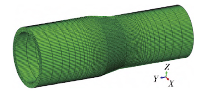
Figure 2 Overall analysis model
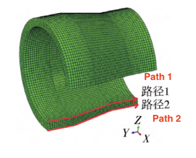
Figure 3 Path distribution
Under pure internal pressure, the stress on the inner surface of the reducer is higher than on the outer surface, with the maximum stress located on the inner surface of the small end bending angle. Under axial tension Fz, the outer surface of the small head bending angle and the inner surface of the large head bending angle are stress concentration areas, with the maximum stress located on the outer surface of the small head bending angle. Under the bending moment Mx, on the neutral surface aligned with the bending moment action surface, the stress concentration area is located at the bending angle. The stress on the outer surface of the small head bending angle is higher than on the inner surface, and the stress on the inner surface of the large head bending angle is higher than on the outer surface, with the maximum stress located on the outer surface of the small head bending angle. Under the torque Nz load, the stress on the outer surface is generally higher than on the inner surface, but in a very small area near the large head bending angle, the stress on the inner surface is higher than on the outer surface. The stress concentration area is located at the small head bending angle, with the maximum stress located on the outer surface of the small head bending angle. The above stress distribution pattern is consistent with previous research results, indicating that the finite element analysis method used in this paper is feasible and can be applied to stress analysis of reducers under subsequent service conditions.
2. Stress analysis of reducers in service
For stress analysis of pipe fittings in service, the high-stress areas can be determined, providing data support and a theoretical basis for safety analysis, failure prediction, and more. For in-service pipe fittings, the high working temperature necessitates the analysis of both the temperature field and stress field, which affect and interact with each other. Typically, for metal materials, thermal stress has little effect on temperature, so only the impact of the temperature field on the stress field needs to be considered. The reducer in the hot section pipeline of a 660 MW ultra-supercritical unit is the research subject, with its layout shown in Figure 4. The reducer is positioned after the first tee of the hot section pipeline leading to the middle main gate branch pipe and is used for pipe diameter reduction. The tee at this position is a forged 45° inclined tee, while the reducer is a steel pipe die-cast reducer.
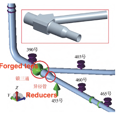
Figure 4 Layout of heat pipe reducers
The design temperature of the hot section pipeline is 618°C. The design pressure is 6.56MPa. The design specification for the hot section main pipe is 883 mm × 57 mm. The design specification for the branch pipe is 616 mm × 41 mm, and the pipeline's design material is A335P92. On-site measurements show that the actual specification of the large-end pipe of the reducer is 1012 mm × 64 mm, while the reducer is 712 mm × 47 mm, with a smooth transition in wall thickness. The main dimensions of the reducer structure are L1 = 100 mm, L2 = 400 mm, and L3 = 100 mm.
Using the No. 390, No. 403, and No. 455 hanging points as boundaries, a partial finite element three-dimensional analysis model that includes a reducer, a 45° forged tee, and a straight pipe is established. The thermo-solid coupling analysis method is used, and a linear elastic constitutive model is adopted. The pipe material's density is 7850 kg/m³, and its Poisson's ratio is 0.3. To facilitate the addition of displacement boundary conditions, reference points RP1, RP2, and RP3 are established at the center of the three end faces of the finite element model (i.e., the center of the No. 390, No. 403, and No. 455 hanging points). The coupling connections between the RP1, RP2, and RP3 reference points and the corresponding end faces are established, and the endpoint displacement calculated by the entire pipe system is added to these reference points.
Considering the characteristics of pipeline installation and operation, two analysis steps (Step 1 and Step 2) are defined. Step 1 simulates the state of the pipeline after initial installation (cold state), while Step 2 simulates the design operation state (hot state). In Step 1, the model temperature is set to 20°C, the pipeline and insulation self-weight loads are applied, and the cold displacement of each endpoint is added as a displacement boundary condition. In Step 2, the model temperature is set to 618°C, the pipeline and insulation self-weight loads are maintained, the pipeline's operating internal pressure of 6.56MPa is applied, and the thermal displacement of each endpoint is added as a displacement boundary condition. The cold and hot displacements of each endpoint are calculated using the CAESAR II pipeline stress analysis software for the thermal expansion of the entire hot section pipeline system (including the low bypass pipeline).
The calculated stress distribution of the overall model is shown in Figure 5. In the cold state, the high-stress area is primarily located at the main pipe weld of the forged tee and the bend angle of the reducer, with a maximum Mises stress of 112.1MPa. The stress level in the tee area is generally low. In the hot state, there is a partial stress concentration area on the inner wall of the shoulder of the forged tee, with the stress concentration in the acute shoulder area being more significant, and the maximum Mises stress reaching 194.4MPa. The stress level in other areas of the tee is generally low, mainly due to the large thickness of the forged tee and its stronger bearing capacity compared to the hot-pressed tee.
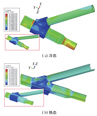
(a) Cold state (b) Hot state
Figure 5 Mises stress distribution of the overall model in cold and hot states
The cold and hot Mises stress distributions of the reducer are shown in Figure 6. The main stress concentration area of the reducer is located at the bending angle. In the cold state, the high-stress area is found on the outer wall of the bending angle at the small head end and the inner wall of the bending angle at the large head end, with a maximum stress of 104.1MPa located on the outer wall of the bending angle at the small head end in the +Z direction. In the hot state, the high-stress area is similarly located on the outer wall of the bending angle at the small head end and the inner wall of the bending angle at the large head end. However, the orientation has changed, with the maximum stress now being 121.6MPa, located on the outer wall of the bending angle at the small head end in the -X/-Z direction. In addition, at the welding seam where the reducer and the straight pipe are connected, the wall thickness of the reducer is greater than that of the straight pipe section. There is a chamfer at the joint, which causes stress concentration in the corresponding area. The yield strength of A335 P92 at room temperature is a minimum of 440MPa, and the tensile strength is a minimum of 620MPa. At a high temperature of 618°C, the yield strength is approximately 260MPa, and the tensile strength is approximately 300MPa. In general, the highest stress in the 45° forged tee and reducer in the model is below the yield strength of the material, and the overall structural stress level of the analyzed parts meets the strength requirements.
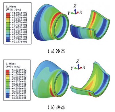
(a) Cold state (b) Hot state
Figure 6 Mises stress distribution of reducers in hot and cold states
Figure 4 Layout of heat pipe reducers
The design temperature of the hot section pipeline is 618°C. The design pressure is 6.56MPa. The design specification for the hot section main pipe is 883 mm × 57 mm. The design specification for the branch pipe is 616 mm × 41 mm, and the pipeline's design material is A335P92. On-site measurements show that the actual specification of the large-end pipe of the reducer is 1012 mm × 64 mm, while the reducer is 712 mm × 47 mm, with a smooth transition in wall thickness. The main dimensions of the reducer structure are L1 = 100 mm, L2 = 400 mm, and L3 = 100 mm.
Using the No. 390, No. 403, and No. 455 hanging points as boundaries, a partial finite element three-dimensional analysis model that includes a reducer, a 45° forged tee, and a straight pipe is established. The thermo-solid coupling analysis method is used, and a linear elastic constitutive model is adopted. The pipe material's density is 7850 kg/m³, and its Poisson's ratio is 0.3. To facilitate the addition of displacement boundary conditions, reference points RP1, RP2, and RP3 are established at the center of the three end faces of the finite element model (i.e., the center of the No. 390, No. 403, and No. 455 hanging points). The coupling connections between the RP1, RP2, and RP3 reference points and the corresponding end faces are established, and the endpoint displacement calculated by the entire pipe system is added to these reference points.
Considering the characteristics of pipeline installation and operation, two analysis steps (Step 1 and Step 2) are defined. Step 1 simulates the state of the pipeline after initial installation (cold state), while Step 2 simulates the design operation state (hot state). In Step 1, the model temperature is set to 20°C, the pipeline and insulation self-weight loads are applied, and the cold displacement of each endpoint is added as a displacement boundary condition. In Step 2, the model temperature is set to 618°C, the pipeline and insulation self-weight loads are maintained, the pipeline's operating internal pressure of 6.56MPa is applied, and the thermal displacement of each endpoint is added as a displacement boundary condition. The cold and hot displacements of each endpoint are calculated using the CAESAR II pipeline stress analysis software for the thermal expansion of the entire hot section pipeline system (including the low bypass pipeline).
The calculated stress distribution of the overall model is shown in Figure 5. In the cold state, the high-stress area is primarily located at the main pipe weld of the forged tee and the bend angle of the reducer, with a maximum Mises stress of 112.1MPa. The stress level in the tee area is generally low. In the hot state, there is a partial stress concentration area on the inner wall of the shoulder of the forged tee, with the stress concentration in the acute shoulder area being more significant, and the maximum Mises stress reaching 194.4MPa. The stress level in other areas of the tee is generally low, mainly due to the large thickness of the forged tee and its stronger bearing capacity compared to the hot-pressed tee.
(a) Cold state (b) Hot state
Figure 5 Mises stress distribution of the overall model in cold and hot states
The cold and hot Mises stress distributions of the reducer are shown in Figure 6. The main stress concentration area of the reducer is located at the bending angle. In the cold state, the high-stress area is found on the outer wall of the bending angle at the small head end and the inner wall of the bending angle at the large head end, with a maximum stress of 104.1MPa located on the outer wall of the bending angle at the small head end in the +Z direction. In the hot state, the high-stress area is similarly located on the outer wall of the bending angle at the small head end and the inner wall of the bending angle at the large head end. However, the orientation has changed, with the maximum stress now being 121.6MPa, located on the outer wall of the bending angle at the small head end in the -X/-Z direction. In addition, at the welding seam where the reducer and the straight pipe are connected, the wall thickness of the reducer is greater than that of the straight pipe section. There is a chamfer at the joint, which causes stress concentration in the corresponding area. The yield strength of A335 P92 at room temperature is a minimum of 440MPa, and the tensile strength is a minimum of 620MPa. At a high temperature of 618°C, the yield strength is approximately 260MPa, and the tensile strength is approximately 300MPa. In general, the highest stress in the 45° forged tee and reducer in the model is below the yield strength of the material, and the overall structural stress level of the analyzed parts meets the strength requirements.
(a) Cold state (b) Hot state
Figure 6 Mises stress distribution of reducers in hot and cold states
3. Conclusion
(1) Using the hot section pipeline of a 660 MW ultra-supercritical unit as the research object, a partial finite element three-dimensional analysis model, including reducers, 45° forged tees, and straight pipes, was established based on the drawing dimensions and measured wall thickness data. Stress simulation analysis under in-service conditions was carried out using the thermal-solid coupling analysis method to obtain the actual stress distribution of the 45° forged tees and reducers. The results show that the high-stress area of the 45° forged tee in the cold state is located near the welding of the end face of the tee’s main pipe. In the hot state, the stress concentration in the sharp-angle shoulder area is significant, while the stress level in the rest of the part is relatively low. This is mainly due to the large thickness of the forged tee, which provides greater bearing capacity compared to the hot-pressed tee.
(2) The main stress concentration area of the reducer is at the bending angle. In the cold state, the high-stress areas are located on the outer wall of the bending angle at the small head end and the inner wall of the bending angle at the large head end. In the hot state, the high-stress areas are similarly located on the outer wall of the bending angle at the small head end and the inner wall of the bending angle at the large head end, but the specific orientation has changed.
(2) The main stress concentration area of the reducer is at the bending angle. In the cold state, the high-stress areas are located on the outer wall of the bending angle at the small head end and the inner wall of the bending angle at the large head end. In the hot state, the high-stress areas are similarly located on the outer wall of the bending angle at the small head end and the inner wall of the bending angle at the large head end, but the specific orientation has changed.
Post URL: https://www.landeepipefitting.com/stress-analysis-of-high-temperature-steam-pipe-reducers-under-service-conditions.html
Landee is a professional industrial pipe fitting manufacturer and be well accepted by customers all over the world, we has been producing Pipe Fitting for a variety of applications since 1985. welcome to access our website: https://www.landeepipefitting.com.
Previous: Stress Analysis of High-temperature Steam Pipeline Reducers
Next: Pictographic Anode for Pipe Fittings
Next: Pictographic Anode for Pipe Fittings
