The Cause Analysis of Perforated Elbows for Cracking Furnaces
Posted: 12/09/2021 10:20:13 Hits: 4
Introduction
There are 8 cracking furnaces in a workshop, from NO.1 to NO.8. Furnaces from NO.1 to NO.7 are a USC-176C tube cracking furnace, and NO.8 furnace is a USC-12M circulating gas cracking furnace, of which the USC-12M circulating gas cracking furnace has the structure of a single furnace (radiation rooms). In September 2017, it was discovered that the 180° casting elbow at the outlet below the furnace tube of NO.8 furnace perforated and leaked. The ambient temperature of the elbow was 1100℃; the pressure was from 0.3 to 0.4MPa, and the medium was cracked gas and diluted steam. The design material was HP MICRO, and the furnace was put into production in October 2012 (Figure 1). HP alloy is a commonly used high-temperature and heat-resistant material for cracking furnaces. Elbows used for HP cracking furnace tubes have a poor working environment. The abnormal shutdown of the cracking furnace caused by the perforation of the alloy elbows causes great economic losses.
1. The detection and analysis
1.1 Macro and low magnification observation
Perforations could be seen on the outer wall of the failure part and were at the shoulder of the elbow. The diameter of the perforation was about 7 mm, and the edge of the perforation part was sharp, indicating that the tube wall was seriously thinned (Figure 2). Observing the inner wall, it is found that the failure part mainly had a shape of a vortex, and obvious advancement traces of fluid vortex could be seen. At the same time, there were obvious pits and pinholes after the scouring of solid particles near the perforated part (Figure 3).
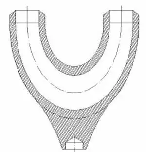
Figure 1 Elbows used for NO.8 furnaces
1.2 The analysis for the material
The chemical composition of the elbow was analyzed with a direct-reading spectrometer, and it was found that the parallel detection effect of many elements was very poor. Among them, the Si and Cr elements were tested multiple times and at multiple points, and the results were quite different, indicating that the organization was not uniform (Table 1). The average content of other elements met the chemical composition required by HP40Nb.
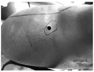
Figure 2 The outer wall morphology of the failure part
1.3 Micro observation
Microscopic observation for the morphology of the inner wall near the failure part showed that the inner wall has obvious cavities, micro-cracks, and pits caused by the impact (Figure 4). Analyzing the surface composition of the inner wall of the failure part, in addition to the metal elements, it also contains elements such as Al, Si, Mn, and O. Combining the process conditions, it could be known that these elements came from the catalyst.
1.4 Metallographic inspection
The metallographic structure of the elbow was mainly an austenite framework, with obvious secondary carbide precipitation between the grains (Figure 5).
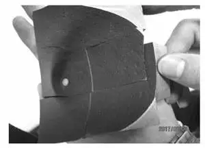
Figure 3 The morphology of the inner wall of the failure part
Table 1 Analysis results of the chemical composition of elbows Wt.%
There are 8 cracking furnaces in a workshop, from NO.1 to NO.8. Furnaces from NO.1 to NO.7 are a USC-176C tube cracking furnace, and NO.8 furnace is a USC-12M circulating gas cracking furnace, of which the USC-12M circulating gas cracking furnace has the structure of a single furnace (radiation rooms). In September 2017, it was discovered that the 180° casting elbow at the outlet below the furnace tube of NO.8 furnace perforated and leaked. The ambient temperature of the elbow was 1100℃; the pressure was from 0.3 to 0.4MPa, and the medium was cracked gas and diluted steam. The design material was HP MICRO, and the furnace was put into production in October 2012 (Figure 1). HP alloy is a commonly used high-temperature and heat-resistant material for cracking furnaces. Elbows used for HP cracking furnace tubes have a poor working environment. The abnormal shutdown of the cracking furnace caused by the perforation of the alloy elbows causes great economic losses.
1. The detection and analysis
1.1 Macro and low magnification observation
Perforations could be seen on the outer wall of the failure part and were at the shoulder of the elbow. The diameter of the perforation was about 7 mm, and the edge of the perforation part was sharp, indicating that the tube wall was seriously thinned (Figure 2). Observing the inner wall, it is found that the failure part mainly had a shape of a vortex, and obvious advancement traces of fluid vortex could be seen. At the same time, there were obvious pits and pinholes after the scouring of solid particles near the perforated part (Figure 3).

Figure 1 Elbows used for NO.8 furnaces
1.2 The analysis for the material
The chemical composition of the elbow was analyzed with a direct-reading spectrometer, and it was found that the parallel detection effect of many elements was very poor. Among them, the Si and Cr elements were tested multiple times and at multiple points, and the results were quite different, indicating that the organization was not uniform (Table 1). The average content of other elements met the chemical composition required by HP40Nb.

Figure 2 The outer wall morphology of the failure part
1.3 Micro observation
Microscopic observation for the morphology of the inner wall near the failure part showed that the inner wall has obvious cavities, micro-cracks, and pits caused by the impact (Figure 4). Analyzing the surface composition of the inner wall of the failure part, in addition to the metal elements, it also contains elements such as Al, Si, Mn, and O. Combining the process conditions, it could be known that these elements came from the catalyst.
1.4 Metallographic inspection
The metallographic structure of the elbow was mainly an austenite framework, with obvious secondary carbide precipitation between the grains (Figure 5).

Figure 3 The morphology of the inner wall of the failure part
Table 1 Analysis results of the chemical composition of elbows Wt.%
| Elements | The tested content of the elbow | Standard content (HP40Nb) |
| C | 0.455 | Between 0.35 and 0.40 |
| Si | 1.60 and 2.48 | Less than and equal to 2.0 |
| Mn | 0.888 | Less than and equal to 2.0 |
| P | 0.005 | Less than 0.03 |
| S | 0.0175 | Less than 0.03 |
| Cr | 20.6 and 24.6 | 24 and 28 |
| Ni | 35.5 | 34 and 36 |
| Nb | 1.46 | 0.8 and 1.5 |
| Ti | 0.103 | - |
| W | 1.36 | - |
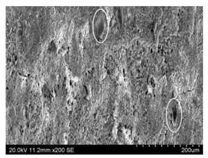
Figure 4 Observing the microscopic morphology of the inner wall near the failure part (with a magnification of 200)
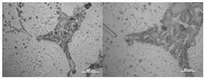
Figure 5 Metallographic structure of the failure part of the elbow
2. The cause analysis of perforation of elbows
By observing the macro and micromorphology of the failure part, it is found that the inner wall had an obvious fluid-oriented arc, and there were cavities and pinholes caused by the fluid's high-speed impact; no obvious corrosion product accumulation was seen on the surface of the elbow. The microscopic morphology of the elbow showed that there was an extruded pit structure on the surface, indicating that the failure of the elbow was related to the scouring and wear of the fluid.
Scouring and thinning of elbows is a common failure. Scouring and thinning is a kind of loss process caused by the scouring on the surface of the elbow by the scattered small pieces of materials in the medium according to a certain angle or speed. According to the physical mechanism of action, this scouring was caused by the airflow carrying small solid particles on the surface of the material, that is, sandblasting scouring, and there was also a slight scouring caused by the airflow carrying small droplets on the surface of the elbow. It could be seen from the energy spectrum analysis that the surface of the failure part could be seen. Combined with the process, the solid coke powder particles were the main material for scouring.
Scouring was mainly affected by the speed, size, fragility, material strength, and physical properties of coke powder particles. The medium with or without solid particles was the most important factor affecting scouring. The path of the coke powder flowing through the elbow was mainly due to the size, weight and medium of the particles as well as the force of the coke powder particles. As long as the light-weight coke powder particles received a small external force, the coke powder could change the direction and flow along the actual direction of the fluid. Large particles often have higher momentum, and it is difficult for the traction generated by the medium fluid to change its direction of movement. When there were large particles, they directly hit the wall of the elbow, and the medium was bounced.
Through other literature analysis of track and pressure distribution of the elbow with different angles, when the medium flowed into the bend, it was blocked by the inner wall of the outer side of the bend, and a small part of the fluid was blocked and compressed, forming a partial high-pressure zone. The greater the angle was, the higher the pressure became. Therefore, the high-pressure zone of the 180° bend was also the highest, that is, when the angle of the elbow was 180, its scouring strength and area were the largest.
The above analysis showed that the medium formed a high-pressure zone on the inner wall of the elbow's outer part, and scoured the inner wall of the elbow, causing a large area of thinning of the wall in the high-pressure zone, forming a failed elbow. The coke powder particles in the mixed medium concentrated on collisions and cutting impacts in a smaller area in the area, making the scouring more serious there; at the same time, the fluid elbow area formed a vortex, which caused the scouring to expand in a deeper direction, eventually led to severe thinning and perforation of the partial area. In addition, high-temperature weakening also happened for the partial metallographic structure of the elbow, which also reduced the scouring resistance performance to a certain extent.
3. Recommendations
The material analysis and metallographic inspection results of the failed 180° elbow showed that the results of the Cr and Si content test couldn't be parallel, and the average value couldn't be obtained, indicating that the composition of the elbow was not uniform. The failure mechanism of the elbow belonged to the partial scouring and thinning; the main reason was the high-pressure zone and a vortex zone formed by powder particles on the inner wall of the elbow's outer side, which eventually led to partial perforation leakage. The solutions are as follows:
(1) According to the actual size and structure of the elbow, the flow pattern can be simulated to confirm the position of the high-pressure zone and vortex zone of the elbow, as a basis for further protection design.
(2) If necessary, the thickness of the single side wall in the vortex zone and high-pressure zone can be changed to improve the wear resistance.
(3) The fluid state and the elbow structure can be compared and analyzed; the structure design can be optimized, and the wear can be solved.
(4) Optimize the process to minimize the scouring and thinning of the elbow by the coke powder particles.
Post URL: https://www.landeepipefitting.com/the-cause-analysis-of-perforated-elbows-for-cracking-furnaces.html
Landee is a professional industrial pipe fitting manufacturer and be well accepted by customers all over the world, we has been producing Pipe Fitting for a variety of applications since 1985. welcome to access our website: https://www.landeepipefitting.com.
Previous: Analysis of Failure Causes of Tees in Inlet Pipelines of Hydrocracking Pumps (Part Two)
Next: Leakages at the Connecting Part Between Flanges & Reducers in Quench Boilers
Next: Leakages at the Connecting Part Between Flanges & Reducers in Quench Boilers
