The Cause Analysis of the Cracking of High-Pressure Steam Pipe Caps (Part One)
Posted: 08/24/2021 11:47:51 Hits: 60
Abstract: The failure of pipe caps of high-pressure steam pipelines caused by cracking was analyzed and checked. After the macro inspection of the whole, inner and outer walls, the fracture, and the microscopic metallographic structure and hardness test, the brittle failure caused by ultra-low temperature conditions, high-temperature damage, graphitization brittle fracture, intergranular corrosion brittle fracture, stress corrosion cracking were excluded. After the final analysis, the cracking of pipe caps was caused by thermal fatigue, and the corresponding corrective measures were proposed for the failure cause.
1. The overview of pipe caps
Leakages happened for the pipe cap on the high-pressure steam pipeline at the inlet of the high-pressure steam turbine of the synthesis gas compressor of the synthetic ammonia equipment in a fertilizer plant due to cracks. The equipment was stopped, and a major accident was avoided. The high-pressure steam pipeline was put into use in 1976 and has been used for 36 years. The pipe has a size of φ355 mm x 23.8 mm, and is made from ASTM335 Grade P11. It is equivalent to 12Cr1MoV in Chinese standards. The pipe cap is made by forging. See Table 1 for its chemical composition. Mechanical properties of SA335 P11 are σb being greater than and equal to 415MPa, and σs being greater than and equal to 205MPa. According to the normalizing heat treatment, the metallographic structure should be ferrite plus pearlite. The steam pressure in the pipeline is 10.5MPa, and the temperature is 430℃.
Table 1 Chemical composition of materials of pipe caps
| Element | C | Mn | P | S | Si | Cr | Mo |
| Content, % | 0.05 to 0.15 | 0.3 to 0.6 | Greater than and equal to 0.025 | Greater than and equal to 0.025 | 0.5 to 1.0 | 1.0 to 1.5 | 0.44 to 0.65 |
2. Inspection and results
2.1 Macro inspection
2.1.1 The overall macro inspection and analysis of the pipe cap
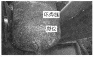
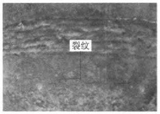
Observing the appearance of the cracked pipe cap, it is found that there was a circular crack on the side of the lower part of the circumferential weld seam on the outer wall of the pipe cap. The crack was not straight, showing a shape of a wave and extending horizontally. The arc length of the annular crack on the outer wall of the pipe cap was 266 mm after measuring, and the crack width was very narrow, only about 0.6 mm. The anti-corrosion paint at the annular crack and the lower area has fallen off severely, as shown in Figure 1 and Figure 2.

Figure 1 The cracked pipe cap
After cutting the pipe cap from the annular welding seam position, it is found that the inner wall of the cap was not corroded seriously, and there was also an annular mark looking like a crack corresponding to the crack on the outer wall. The length of the arc measured was about 90 mm. According to the macro morphology of the outer wall and inner wall of the pipe cap, a comparison of the crack length and crack width, it could be preliminarily judged that cracks of pipe caps started from the outer wall and expanded toward the inner wall.

Figure 2 The morphology of cracks on the outer wall of the pipe cap
2.1.2 Macroscopic inspection and analysis of the inner and outer walls of the sample of the pipe cap
Took 5 specimens at the crack of the pipe cap, two of which had cracks on both sides (not penetrating cracks); three of which had cracks in the middle area (penetrating cracks). Used a stereo microscope to observe the surface morphology of the outer and inner walls of the sample, and it is found that the wavy annular crack of the outer wall of the cap penetrated the entire wall thickness and merged into a relatively straight crack after reaching the inner wall. This was the suspected crack observed on the inner wall of the pipe cap. It can be seen from the macroscopic morphology of the sample without penetrated cracks, there was a circular crack on the outer wall of the pipe cap, but no crack was found on the inner wall; the crack on the outer wall of the pipe cap stopped when it was close to the inner wall. These proved that the cracks in the caps originated on the outer wall and expanded in the direction of the inner wall.
2.1.3 Macroscopic inspection and analysis of the fracture of the sample of the pipe cap
Broke the 3 samples with penetrating cracks, and cleaned them with an ultrasonic cleaner. Observed the macroscopic fracture of the sample with a stereo microscope. The results showed that the fracture of the pipe cap showed a brittle fracture morphology as a whole; one side of the outer wall of the fracture was uneven, and there were crack propagation steps formed by the convergence of multiple crack sources. One side of the inner wall of the fracture was relatively smooth, and there was a fresh zone on the inner wall where a narrow sample broke when the sample was broken. This fully proved that the crack in the pipe cap expanded from the outer wall to the inner wall. From the macro morphology of the fracture surface of the cracked sample of the cap, it can be inferred that the cracking of the pipe cap was a delayed crack which was incubated and expanded after a long period of time. The fracture morphology showed brittleness, which was in line with the characteristics of stress corrosion cracking or fatigue cracking (high-temperature fatigue or thermal fatigue).
2.2 Microscopic inspection and analysis
2.2.1 Microscopic inspection and analysis of the fracture of the crack sample of the pipe cap
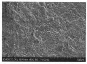
The three crack fracture samples of the pipe cap were sprayed with metal for conductive treatment with ion sputtering instrument, and the surface micromorphology of the fracture of the samples was observed and analyzed by an imported scanning electron microscope and energy spectrometer. See Figure 3. The detected composition of corrosion products on the surface is shown in Table 2.

Figure 3 The micro morphology of the fracture surface of the pipe cap (500 times)
Table 2 The composition of corrosion products on the fracture surface of the pipe cap
| Element | C | O | Mn | Fe |
| Content, % | 1.59 | 21.49 | 0.75 | 76.17 |
From the low magnification microscopic morphology of the fracture surface of the pipe cap, it can be seen that no features of secondary cracks of stress corrosion were found on the fracture surface. The low magnification microscopic morphology of the fracture showed a fatigue band morphology. The high magnification microscopic morphology of the surface (Figure 3) showed that the fracture surface was covered with a layer of corrosion products. From the test results of the corrosion product composition in Table 3, it can be seen that the corrosion products on the fracture surface were mainly iron oxides, and no sulfide and chloride were found.
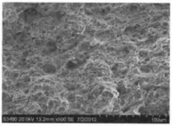
Figure 4 shows the high magnification microscopic morphology of the fresh zone of the fracture formed when the cap crack was broken. It can be seen that the microscopic morphology of the fracture surface was a dimple. This was the microscopic morphological feature of plastic fracture, indicating that there was no serious embrittlement for the cap's material.

Figure 4 The microscopic morphology of the fresh area of the fracture of the pipe cap (500 times)
Post URL: https://www.landeepipefitting.com/the-cause-analysis-of-the-cracking-of-high-pressure-steam-pipe-caps-part-one.html
Landee is a professional industrial pipe fitting manufacturer and be well accepted by customers all over the world, we has been producing Pipe Fitting for a variety of applications since 1985. welcome to access our website: https://www.landeepipefitting.com.
Previous: Reducing Cracks through the Manufacture and Post Treatment of Bends
Next: The Cause Analysis of the Cracking of High-Pressure Steam Pipe Caps (Part Two)
Next: The Cause Analysis of the Cracking of High-Pressure Steam Pipe Caps (Part Two)
